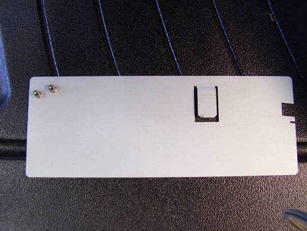
The following instructions will guide you through checking and, if necessary, adjusting the X-Cable tension on your AMAYA XT or BRAVO machine. The X-Cable Tension Gauge (Melco PN 33909), shown in picture 1 below, is used to indicate the permissible range for proper X-Cable tension.
Pic. 1: X-Cable Tension Gauge, Melco PN 33909
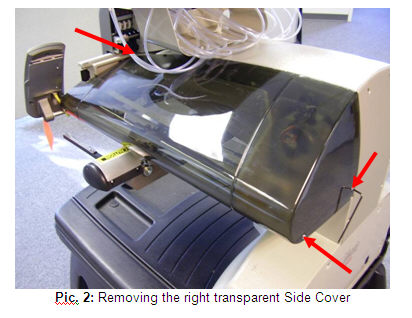
1. Remove the right transparent Side Cover shown in picture 2 below. Using a 4mm bent Allen wrench, remove the three indicated screws and carefully remove the Side Cover.
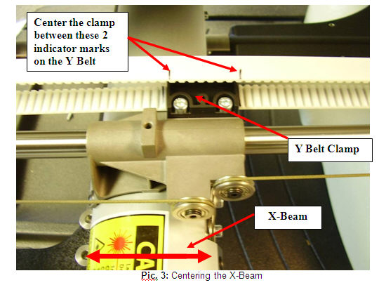
2. Center the Y Belt Clamp between the two black indicator marks on the Y Belt, as shown in picture 3 below, by moving the X-Beam forward or back.
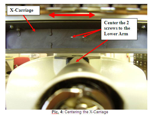
3. Move the X-Carriage left or right until the two screws indicated in picture 4 below are centered to the Lower Arm.
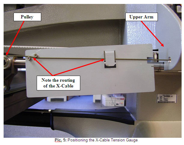
4. Position the X-Cable Tension Gauge on the X-Cable as shown in picture 5 below. Center the Gauge between the indicated Pulley and the Upper Arm.
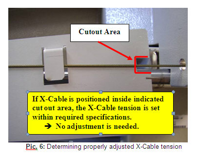
5. A properly adjusted X-Cable will fall within the cutout area shown in picture 6 below. If the X cable falls within the cutout area, remove the fixture and re-install the Side Cover.
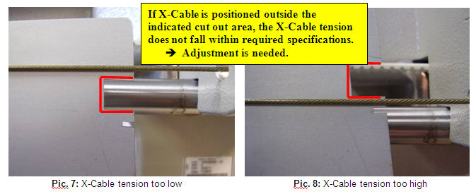
6. An improperly adjusted X-Cable will be positioned outside, either above (tension too low) or below (tension too high), the cutout area as shown in pictures 7 and 8 below. In this case the tension of the X-Cable requires adjustment. Follow steps 1-5 in section B below to properly adjust the tension of the X-Cable.
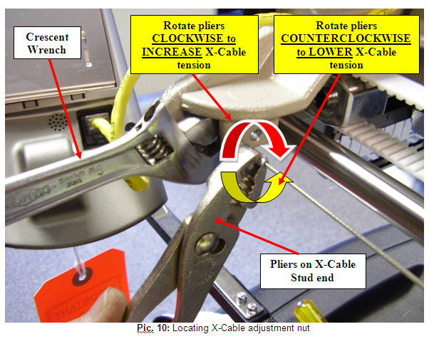
1. Locate the M4 Nut and the X-Cable Stud at the end of the X-Cable where it mounts to the front of the Upper Arm as shown in picture 9 below.
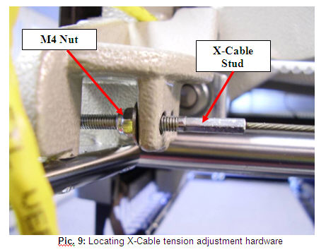
2. Using a small Crescent wrench grip the M4 Nut (shown in picture 9 above) and with a pair of pliers grip the X-Cable Stud at the end of the X-Cable as shown in picture 10 below.
3. Remove the wrench and pliers and move the X-Beam full travel to the front and back and the X-Carriage full travel left and right a few times to ensure proper settling of the X-Cable tension.
4. Repeat steps 2 – 5 in section A and verify that the X-Cable is now adjusted to required specifications. If the X-Cable tension is adjusted properly, remove the fixture and re-install the Side Cover. If the X-Cable tension is still not adjusted properly, repeat steps 1-4 in section B until the X-Cable tension is adjusted correctly.
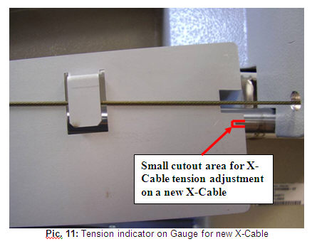
1. If a new X-Cable had to be installed on the machine, the initial X-Cable tension adjustment should align the X-Cable with the small cutout area on the X-Cable Tension Gauge as shown in picture 11 below.
2. Follow steps 1-4 in section A to properly position the X-Cable Tension Gauge on the X-Cable.
3. Follow steps 1-3 in section B to adjust the tension in the X-Cable until the X-Cable aligns with the small cut out in the X-Cable Tension Gauge as shown in picture 12 below.
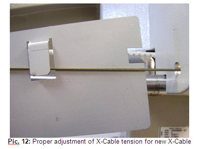
4. After initial adjustment of the tension in the new X-Cable the X-Cable will stretch (= X-Cable tension will decrease) to a point where the X-Cable will fall within the required operating range as shown in picture 6.