![]()
The grabber/threadfeed motor harness connects the grabber and thread feed stepper motors to the connector socket at location J33 on the main PCB. The grabber/threadfeed motor harness has two leads coming off of it, one labeled "THREAD FEED MOTOR" and the other labeled "GRABBER MOTOR". These leads connect to the interface cables coming off the respective stepper motors.
Replacement Parts Needed:
harness, grabber/threadfeed
twist-lock cable ties (available from most hardware stores in the electrical section)
Replacement Procedures:
1. Turn the machine on.
3. Turn the machine OFF.
|
|
CAUTION!! Use extreme care not to drop metallic objects, tools, or other conductive material on the Main PCB when you have the base cover removed. If you drop such objects on the Main PCB, it can severely damage the electronics which will be very expensive to repair. |
4. Remove the right transparent arm cover, base cover, upper arm back cover, and lower arm rear cover.
5. Cut any cable ties bundling the grabber motor lead behind the left side of the needlecase assembly.
|
|
CAUTION!! When disconnecting the harness leads, grab the connectors. Do not pull on the wires. You will damage the harness if you do. |
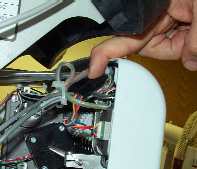
Figure 1 - Grabber Motor Lead
6. Disconnect the grabber lead from the grabber motor interface cable.
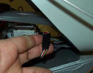
Figure 2 - Thread Feed Motor Lead
7. On the left side of the needlecase, remove any twist-lock cable ties bundling the thread feed motor lead to adjacent harnesses.
8. Disconnect the thread feed lead from the thread feed stepper motor interface cable.
9. Remove the twist-lock cable tie behind the thread tree that bundles the harness running under it.
10. From the backside, pull the grabber and thread feed motor leads through to the back.
11. Remove any twist-lock cable ties that bundle the grabber/thread feed motor harness to the adjacent harnesses and pull the harness from the wiring channel down to where it enters the access cover towards the main PCB.
|
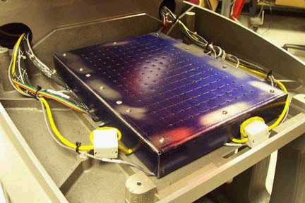
Figure 3a - 32188 Series EMI Cover |
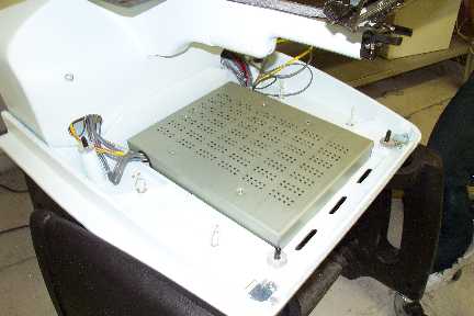
Figure 3b - 32232 Series EMI Cover |
12. Remove the EMI cover from the main control board by removing the screws from the edge of the cover.
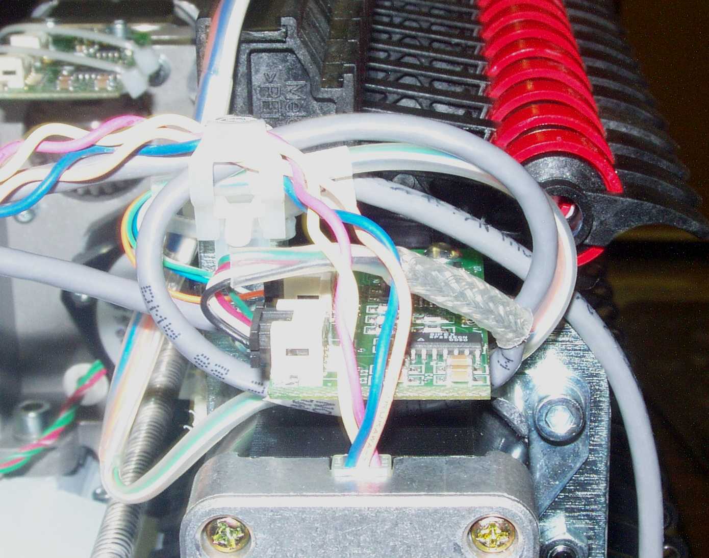
Figure 4 - Grabber/Thread Feed Motor Connection at PCB
13. Disconnect the grabber/thread feed motor harness from the Main PCB at connector location J33.
14. Remove any remaining twist-lock cable ties bundling the grabber/thread feed motor harness to adjacent ones and remove it.
15. Run the grabber motor and thread feed motor leads of the replacement grabber/thread feed motor harness under the thread tree base from the right side of the machine.
16. From the front side of the thread tree, split off the two motor leads, and turn them towards the respective motors.
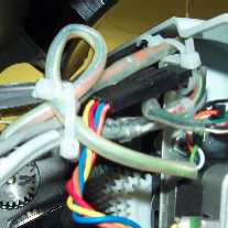
Figure 5 - Harness Tie at Top Left of Needlecase Assembly
17. Connect the grabber motor lead to the interface cable coming off the grabber stepper motor. Loop it and tie it with a cable tie as shown in Figure 4 above. Allow just enough slack so that the connectors will not disconnect during machine operation.
18. Connect the thread feeder motor lead to the interface cable coming off the grabber motor on the right side of the machine.
19. Use a twist-lock cable tie and tie the harnesses running under the thread tree base right at the front and at the back of the base.
20. Run the harnesses running out from under the thread tree base to the right wiring channel and bundle them together with a cable tie at the point where they meet the other harnesses running into the wiring channel.
21. Run the grabber/thread feed motor harness down the right wiring channel following the path of the adjacent harnesses all the way down to the access hole to the Main PCB.
22. Connect the grabber/thread feed motor harness to the connector socket at J33 on the Main PCB.
23. Replace the EMI Cover following the procedures for "EMI Cover - 32232 Series" or "EMI Cover - 32188 Series" (see Figure 3a and 3b for pictures of the EMI covers), as appropriate.
24. Install the covers in the reverse order that you removed them.
25. Conduct machine functional tests to verify that the harness is good and properly connected (the grabber and thread feed motors function).
![]()