![]()
|
|
WARNING!! This procedure is intended to be performed only by specially trained Melco service technicians and personnel. Disassembly by untrained individuals will void any warranty protection and can result in personal injury or damage to the machine.
|
1. Disconnect the red, black and green wires from the back of the switch.

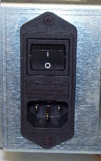
Figure 1 - Power Input Switch (with fuse)
2. Remove the two black M3x0.5x8mm Phillips screws that mount the switch assembly to the power input assembly mounting plate. The screws have loctite applied so be careful when you remove them to avoid stripping them.
3. Apply red loctite (MS 222) to the screws and install the replacement switch in the position shown in Figure 1 above. Tighten the screws to Melco Torque Specifications.

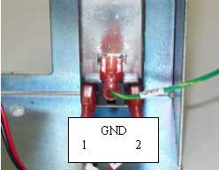
Figure 2 Power Input Switch Wiring
4. Attach the red, black and green connectors from the power switch interface harness and ground cable to the back of the power switch as shown in Figure 2 above. The leads are labeled as indicated by the text below each connection.