 Ruler and Grid Tools
Video
Ruler and Grid Tools
Video
This section describes the basic tools in DesignShop that provide assistance as you edit and/or digitize.
Ruler and Grid Tools
Video

This is a very useful tool if you would like to measure elements. This function is located as a toolbar button and also under the View menu (View->Ruler). You can change the units of measure by selecting Tools->Options, then clicking on the Measurement Units tab. Look for Ruler in the list and select your preferred measurement units (left-click in the radio button).
To use this feature, first click the Ruler toolbar button. Then click on the starting point from which you would like to measure and drag your mouse to the endpoint of your measurement. While doing this look on the bottom of your screen on the status bar to view the measurement. Let go of your mouse button to start a new measurement. To turn off the Ruler feature, click on the Ruler toolbar button again.

You can also press Alt+ R on your keyboard to access this tool.

Clicking the Show Grid button displays a framework of evenly spaced vertical and horizontal black (default color) lines behind the design in the View Window. (Click the Show Grid button again to turn off the grid).
The default setting for the spacing of the grid is 0.5 inches. All default settings can be changed by right-clicking the tool and entering the Grid and Origin properties dialog (See Grid and Origin Properties below).
You can also display/turn off the grid by selecting View->Show Grid.
See Aligning for information on using the grid as an alignment tool.

Clicking the Show Origin button displays two lines along the center X and Y axis of the View Window. The intersection of the two lines indicates the location of the origin and center of the design. When you center your design, it will be centered at this origin. All default settings can be changed by right-clicking the Show Origin tool and entering the Grid and Origin properties dialog (See Grid and Origin Properties).
You can also display/turn off the design origin by selecting View->Show Origin.
To view Grid and Design
Origin properties, right-click the Show
Grid or the Show
Design Origin toolbar button.
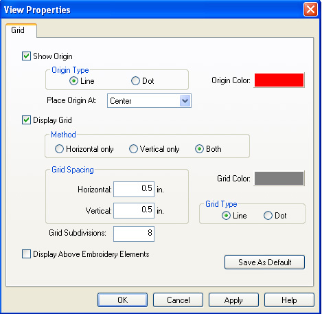
Show Origin: You can click in the box next to Show Origin to display or not display the origin lines in the View Window. A check mark in the box symbolizes that the origin lines will be displayed, whereas no check mark symbolizes that the origin lines will not be displayed.
Origin Color: If you would like to change the color of the origin lines, click on the box next to Origin Color: This will take you to a color dialog where you can choose another color, then click OK. The default color is black.
Place Origin At: Allows you to place the origin at the Center or the First Stitch.
Origin Type: You can choose whether you would like the origin lines to be displayed as lines or as dotted lines. To do this, left-click the radio button next to the desired choice.
Grid: You can click in the box next to Display Grid to display or not to display the grid lines in the View Window. A check mark in the box symbolizes that the grid lines will be displayed, whereas no check mark symbolizes that the grid lines will not be displayed.
Grid Color: If you would like to change the color of the grid lines, click on the box next to Grid Color:. This will take you to a color dialog where you can choose another color then click OK. The default color is gray.
Grid Spacing: This gives you the option to change the spacing between the grid lines. Click in the white area next to Horizontal: to change the spacing between the horizontal lines. After clicking in the white area simply type in a desired measurement. You can also use the up and down arrows to change the measurement value. Click in the white area next to Vertical: to change the spacing between the vertical lines.
Grid Type: You can choose whether you would like the grid lines to be displayed as lines or as dotted lines. To do this, click in the radio button next to the desired choice.
Method: This gives you the option to display only horizontal lines, only vertical lines, or both horizontal and vertical lines. To do this, click in the radio button next to the desired choice.
Grid Subdivisions: Allows you to specify how many subdivisions are seen in your grid.
Display Above Embroidery Objects: Click in the box next to this option to display the grid and origin lines above the embroidery that is in the View Window. A check mark in the box symbolizes that the lines will be displayed in front of (above) the embroidery, whereas having no check mark in the box symbolizes that the lines will be behind the embroidery.
Save As Default: Any time that you change a setting or settings and click the Save As Default button, your changes will be saved. Even if you exit out of DesignShop and get back in again, your default settings will be saved.

Clicking this toolbar button will generate the stitches of a design in the View Window in a three dimensional perspective. (Click this button again to turn this feature off). This will give you a general idea of how the design will look when sewn.
You can print a design in 3D view after pressing the View Stitches in 3D button, then print.
You can also hold down the ALT key and press 3 to turn on View Stitches in 3D.
You can press the view in 3D button, save a design file as a graphic file (*.bmp, *.pcx, *.jpg, *.tif) and give this file to anyone wanting to view what the sew out will look like. The graphic file can be opened in any graphics program, i.e. Paint, Paintshop, Photoshop, etc.
You can customize your 3D view by right-clicking on the 3D button . You will see the following dialog:
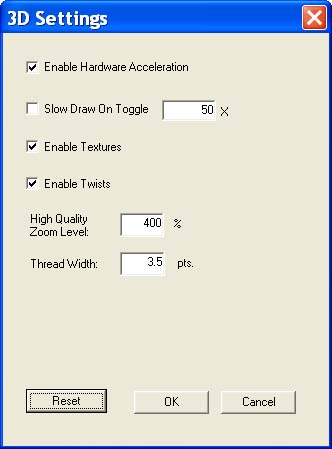
Enable Hardware Acceleration: Allows you to use 3D acceleration with your video card. The default in that this control is enabled.
Slow Draw on Toggle: Check this box if you want your graphic to be drawn slowly in 3D as opposed to instantly.
Enable Textures: Check this box to enable texture in your 3D graphic.
Enable Twists: Check this box to enable twists in your 3D graphic.
High Quality Zoom Level: Allows you to set the level at which your graphic switches to high quality zoom and renders the image at a higher quality.
Thread Width: Controls the width of your thread in your 3D graphic.
Reset: Resets all the settings for your 3D customization.

Click this toolbar button to hide the stitches in an element or design. This tool will hide all of the stitches in selected item(s). (Click again to show the stitches.)
NOTE: To hide stitches in unselected items, select View->Hide Non-selected. To show all stitches again, select View->Show All.

Click these toolbar buttons to change the stitch direction in all column objects. This button also allows you to change stitch direction AND flow in True Type Fonts. To add a stitch direction line, simply click and drag where you want the line to go. To modify a point in True Type fonts, hold down the Shift key and drag the point to change the stitch direction. To insert a break in a True Type Font, hold down the Alt key and click where you want the break to be inserted. To change column break points, click and drag your line inside the object to change the path. To delete a stitch direction point, in either a column object or a True Type font, select the stitch direction point and hit Delete.
To get a pop up menu that allows you to select an editing
mode, click the Stitch Direction Editing
Mode tool  , right-click on the object and the pop
up menu appears (see below).
, right-click on the object and the pop
up menu appears (see below).
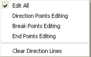
Edit All: Allows all editing types.
Direction Points Editing: Only allows you to edit direction points and hides all other objects.
Break Points Editing: Only allows you to edit break points and hides all other objects.
End Points Editing: Only allows you to edit column end points and hides all other objects.
Clear Direction Lines: Deletes all displayed direction lines.
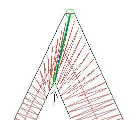
Procedure for capping a Complex Column or a True Type Font:
Click the Stitch
Direction Editing Mode tool .
Click and drag break points to the desired point.
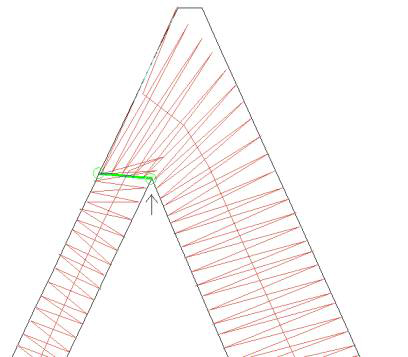
Hold the Control key and click the point with the arrow pointing to it (see above). This caps the object. This is your end result:
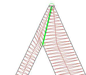
To miter a Complex Column or a True Type Font:
Go to Break Points Editing mode.
Left-click and drag the mouse to the desired point.
Hold the Control key and click the point with the arrow pointing to it to miter the object. This is your end result:
Besides pressing the toolbar button to use zoom in, you can also use a keyboard shortcut by pressing + on your keyboard.
Graphical Zoom in
 allows you to click and drag a box around the area that
you would like to zoom in on. This operation is more specific than Zoom
in.
allows you to click and drag a box around the area that
you would like to zoom in on. This operation is more specific than Zoom
in.
Zoom in  enlarges the design on the screen. It does not affect sewing
size.
enlarges the design on the screen. It does not affect sewing
size.
Zoom out  decreases the design size on the screen. It does not affect
sewing size.
decreases the design size on the screen. It does not affect
sewing size.
Zoom actual
 displays on the screen the actual sewing size of a design.
After changing the design view, click this tool to bring the design view
back to its actual sewing size.
displays on the screen the actual sewing size of a design.
After changing the design view, click this tool to bring the design view
back to its actual sewing size.
Zoom to fit
 will increase or decrease the design size to fit the
entire design on the screen. Click this tool to display the full design.
It does not affect sewing size.
will increase or decrease the design size to fit the
entire design on the screen. Click this tool to display the full design.
It does not affect sewing size.
Fit Selection Zoom
 allows you to zoom in on a specific area that you would
like to edit. After you have an area selected to edit, click on the fit
selection tool.
allows you to zoom in on a specific area that you would
like to edit. After you have an area selected to edit, click on the fit
selection tool.
Center Selection
 allows you to scroll the view to center all currently
selected objects. The objects will be centered in the main view window
without changing the current zoom level.
allows you to scroll the view to center all currently
selected objects. The objects will be centered in the main view window
without changing the current zoom level.
Zoom previous
 will return the design size on screen to the previous
zoom level. It does not affect sewing size.
will return the design size on screen to the previous
zoom level. It does not affect sewing size.
You can find all of the Zoom functions in two locations: as buttons on the View toolbar or as menu items under the View Menu.
Keyboard Shortcuts:
Zoom Out -
Zoom Actual A
Zoom to Fit F
Zoom Previous L
DesignShop allows you to scroll and zoom the main view window using your mouse wheel, if you have one. The various functions are selected by rolling the mouse wheel while holding down various keys. The mouse wheel commands are only set for the current window. The following commands work only if you have clicked on the main view window:
Scroll Vertical: To scroll up and down, the mouse wheel is rolled with no keys held down.
Scroll Horizontal: To scroll left or right, the mouse wheel is rolled while holding the Ctrl key. Also, if you lay the cursor on the horizontal scroll bar and move the mouse wheel, the screen moves from side to side.
Zoom In/Out: To zoom in and out, the mouse wheel is rolled while holding down the Alt key.
Zoom In/Out to Cursor: Position the mouse over the area of the design to zoom, hold down the Shift and Alt keys, and roll the mouse wheel. The view will zoom to the area under the mouse pointer.
DesignShop allows you to move objects on the screen utilizing the Shift, Alt, and Ctrl keys.
Shift: Hold down the Shift key and use the arrow keys to move an object around the screen in very small increments. Use this function to reposition an object to exactly where you want it in a design.
Shift + Alt: Hold down the Shift and Alt keys and use the arrow keys to move an object around the screen in slightly bigger increments than when you use just the Shift key and the arrows.
Shift + Ctrl: Hold down the Shift and Ctrl keys and use the arrow keys to move an object around the screen in the biggest increments. Reposition the object to exactly where you want it in the design.
Shift + Enter: Hold down the Shift key and press Enter to close an outline.
Enter: Press the Enter key to end an outline.
Space + Click: Press the Space bar and click with your mouse to curve points for one button digitizing tablets.

To use this tool, select the graphic, then click the Custom
Point Selection toolbar button . Using the custom
selection cursor, within the selected element, left-click as many times
as necessary to outline the area you wish to select (you can also left-click,
then drag the mouse to outline the points).