
This section explains how to digitize fills in DesignShop. The complex fill types discussed in this section are Standard and Pattern. You can also digitize with Satin Stitch and Decorative Stitch fills. Please see Satin Stitch Fills for information on Satin Fills and Decorative Stitch Fills for information on Decorative Stitch fills.
Setting Complex Fill Properties Video
Unafill Input Mode Video
Digitizing Complex Fills Video
(Available in DesignShop and higher product levels)
To digitize a complex fill, select the complex fill tool by left-clicking it in the toolbar, by selecting Insert->Complex, or by right-clicking inside the View Window and selecting Complex from the pop-up menu.
You can change complex fill properties such as stitch type in the Fill Properties dialog. You can change these properties before you begin digitizing a complex fill by right-clicking the Complex Fill toolbar button and adjusting the element properties.
You can also edit the properties of existing complex fills at the design, project, and element level. See Fill Properties, for a description of fill properties. (Also see Pattern Fills, Standard Fills, and Decorative Stitch Fills.)
Follow the below procedure to digitize a complex fill. Remember that the status bar directly below the design contains instructions to guide you through the steps.
Select the complex fill tool.
Input the wireframe outline of the complex fill by inputting straight (left-clicking) or curved (right-clicking) points. (The last point input should end up being close to the first point that you input).
Press ENTER on your keyboard. This will connect the last point with the first point.
If there are any small holes or places that you do not want the fill to cover, digitize a wireframe outline around those just as you did the first outline and press ENTER after each one. After you have finished digitizing the complex fill and any holes, press ENTER again.
Input the complex fill entry point with a left-click. The entry point is where you would like the stitches to begin on the complex fill.
Input the complex fill exit point with a left-click. The exit point is where you would like the stitches to tie off and end the complex fill.
Input the first direction point with a left-click.
Input the second direction point with a left-click. The direction of the line between the two direction points determines the direction of the fill stitches on the complex fill just digitized. The direction points can be anywhere in the View Window (inside or outside of the complex fill).
The stitches will now be generated in the complex fill.
To Define Endpoints in a Complex Fill:
After your complex fill is digitized and you have set your entry and exit points, instead of inserting stitch direction by left-clicking and dragging, you can right-click and drag where you want your endpoint to be.
A red, dotted line appears where you dragged in the complex fill.
Right-click and drag again to define the other endpoint of the complex fill, if you want both endpoints to be defined. (NOTE: You do not have to define any endpoints in your complex fill. You can also go back at any time and define the endpoints in a complex fill.)
Complex fill automatically terminates after the second direction point is put in.

You can always refer to the status line below the View Window to give direction for the next step while digitizing an element.

(Available in DesignShop and higher product levels)
If you have finished a complex fill and decide later that it should contain some empty spaces (holes), you can insert them without having to digitize the fill again. The toolbar button next to the complex fill button (with the black outline and the filled in hole) is the Insert Outline Tool button.
To digitize a complex hole:
Select the complex fill you want to change by left-clicking inside of it. Remember that you can determine if an element is selected if it has a box around it and its wireframe points are shown.
Select the insert outline tool  .
.
Now digitize the wireframe outline of the hole (following the same procedure as a complex fill).
When finished, press ENTER.
(Available in DesignShop and higher product levels)
There are 16 pre-defined fills containing from 1 to 8 partitions in various combinations of fill parameters.
For more information on standard fill properties, see Standard Fills.
Right-click on the complex fill element ![]() from the side toolbar.
from the side toolbar.
Choose Fill from the Stitch Type drop-down menu
Choose Standard under Fill Info.
Click OK.
Digitize the outline of the shape using the complex fill digitizing rules. (See Complex Fill above).
There are many factors that may be manipulated to form various "looks" in fill stitching. You can change these factors to create your own standard fill.
These factors are stitch density, stitch length, partition lines, partition line sequences, and partition line angles.
Stitch density: how many embroidery points there are between rows of stitches (example: 4.2 points). The image below displays stitch density.
Stitch length: the distance set for maximum length between needle penetrations. The image below displays stitch length.
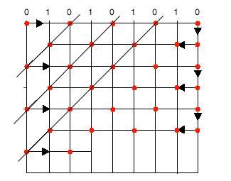
Number of Partition Lines: Partition lines is a mathematical term, and the lines are seen only by the computer. The partition lines are used to determine where the needle will penetrate on each stitch line. Partition lines are numbered beginning with 0; you can enter up to 8 partitions in this field.
Each row of stitching consists of needle penetrations made from one partition line. The number of rows in a partition line set always equals the number of partition lines. In the example below, the number of partition lines is 2; therefore 2 rows of stitching make up the partition lineset. The two partition lines in the illustration are numbered 0 and 1.
In the 1st stitch line, the needle penetrates at the intersection of the stitch line and partition line 0.
In the 2nd stitch line, the needle penetrates at the intersection of the stitch line and partition line 1.
The needle repeats this sequence each 2 stitch lines.
The partition line sequence is 0,1,0,1,0,1, etc.
Partition Line Sequence: If you look closely at the finished fills, you will be able to distinguish a visual pattern. You can vary this pattern by changing the stitch length and density, and by changing the angle of the partition lines; but going one step further, you can change the sequence of the partition order, i.e., 0, 1, 2, 3, 4, 5, 6, 7. For example, you could change the sequence in the previous example to 1,0,1,0, etc.
NOTE: When you create your own partition sequence, if you include a number that is higher than the number of partition lines, that number will be ignored. For example, if you choose 6 for the number of partitions, a 7 in the partition sequence would be ignored.
Partition Line Angle: The angle made by the intersection of any given partition line with the line of stitching in a fill pattern. The angle is measured in a counter-clockwise rotation from the left end of the line of stitching. The angle can be any number between 1 degree and 179 degrees.
In the example below, the partition line angle is 45 degrees, because each stitch point of the partition lines up at an offset that makes a 45 degree angle when a line is drawn through each stitch point of the partition line.
![]()