![]()
|
|
WARNING!! This procedure is intended to be performed only by specially trained and authorized Melco service technicians and personnel. Disassembly by untrained individuals will void any warranty protection and can result in personal injury or damage to the machine.
|
|
|
WARNING!! DO NOT allow the laser beam to be aimed at yours or anyone else's eyes. The laser emits a very concentrated light beam that can cause permanent blindness. Use extreme care in handling the laser assembly to make sure it is not going to be inadvertently aimed at someone's eyes or face. DO NOT LOOK DIRECTLY AT THE LASER LENS WHILE IT IS ENERGIZED! |
The laser harness connects the laser pointer assembly to the Main PCB at connector location J30.
Replacement Parts Needed:
harness, laser
twist-lock cable ties (available at most hardware stores in the electrical section)
Replacement Procedures:
2. Turn the machine OFF.
3. Remove the right upper arm front cover.
4. Remove the right transparent arm cover and the back screw of the left.
|
|
CAUTION!! Use extreme care not to drop metallic objects, tools, or other conductive material on the Main PCB when you have the base cover removed. If you drop such objects on the Main PCB, it can severely damage the electronics which will be very expensive to repair. |
5. Remove the base cover, upper arm back cover and lower arm rear cover.

Figure 1 - Laser Harness Connection to Laser Pointer Assembly
|
|
CAUTION!! When disconnecting the harness DO NOT pull on the wires. Handle only the connector housings. You will damage the harness if you pull on the wires themselves. |
6. Disconnect the laser harness from the laser pointer assembly.
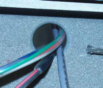
Figure 2 - Right Upper Arm Access Hole
7. From behind the upper arm, pull the laser harness through the right upper arm access hole.
8. Pull the laser harness out the right wiring channel and remove any twist-lock cable ties that bundle the laser harness to adjacent harness, down to the back of the machine.
|
Figure 3a - 32188 Series EMI Cover |
Figure 3b - 32232 Series EMI Cover |
9. Remove the EMI cover from the main control board by removing the screws from the edge of the cover.
10. Disconnect the laser harness from the connector at J30 on the Main PCB and cut any remaining wire ties that bundle the laser harness to adjacent harnesses.
11. From behind the right upper arm, run the harness lead that is labeled "LASER" through the right upper arm access hole and connect it to the laser pointer assembly as shown in Figure 1.
12. Right behind the right upper arm, pull the unneeded slack out of the harness, and use a twist-lock cable tie to bundle the laser harness to the other two adjacent harnesses that run through the hole.
13. Run the laser harness down to the right wiring channel following the same path as the adjacent harnesses in the channel down to the Main PCB and connect the end labeled "CONTROL PCB LASER - J30" to the connector socket at location J30 on the Main PCB.
14. Replace the EMI Cover carefully following the instructions provided in "EMI Cover - 32232 Series" or "EMI Cover - 32188 Series" (see Figures 3a and 3b for pictures of the covers).
15. Replace all twist-lock cable ties.
16. Install the right upper arm front cover and tighten the screws to Melco Torque Specifications.
17. Turn the machine ON.
18. Turn the laser on and off to make sure the laser assembly and harness is working.
19. Install the covers to the machine in the reverse order that you removed them and tighten the screws to Melco Torque Specifications.
![]()

