![]()
Replacement Parts Needed:
harness, trimmer motor
twist-lock cable ties (available from most hardware stores in the electrical section)
Replacement Procedures:
1. Turn the machine OFF.
|
|
CAUTION!! Use extreme care not to drop metallic objects, tools, or other conductive material on the Main PCB when you have the base cover removed. If you drop such objects on the Main PCB, it can severely damage the electronics which will be very expensive to repair. |
2. Remove the rear lower arm cover and the base cover.
3. Remove any twist-lock cable ties and/or zip ties that bundle the trimmer harness to the adjacent ones.
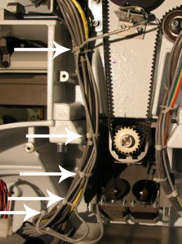
Figure 1 - Trimmer motor harness
4. Loosen the screws on the clamp blocks.
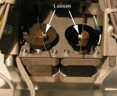
Figure 2 - Loosen Cable Screws
5. If necessary, remove the entire trimmer drive assembly from the lower arm casting by removing the two screws from the trimmer drive bracket with a 5mm Allen wrench.
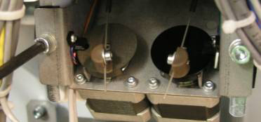
Figure 3 - Remove Trimmer Drive Assembly
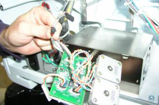
Figure 4 - Remove Trimmer Drive Assembly
6. Some machines may contain a trimmer motor PCB while other machines may not. If the machine contains a trimmer motor PCB, then remove the motor harness from the trimmer motor PCB and the Z-Home PCB. If the machine does not contain a trimmer motor PCB, then remove the motor harness from the motor.
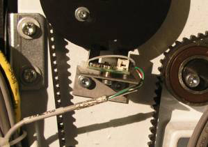
Figure 5 - Z-Home PCB
7. Locate the trimmer motor harness from the backside of the machine in the lower arm wiring channel.
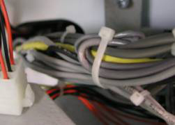
Figure 6 - Lower Arm Wiring Channel
8. Remove the EMI shield.
9. Pull all three harnesses through the right wiring channel from the front of the lower arm casting and disconnect them from the main PCB at locations J32 and J35.
10. Some machines may contain a trimmer motor PCB while other machines may not. If the machine does not contain a trimmer motor PCB, then skip this step. If the machine does contains a trimmer motor PCB, then attach the new harness labeled "Control PCB Trimmer/Z-Home J32" to the main PCB connector socket at J32.
11. Attach the new harness to the main PCB connector socket at J35. (For machines that contain a trimmer motor PCB, the harness will be labeled "Control PCB Trimmer/Z-Home J35". For machines that do not contain a trimmer motor PCB the harness will be labeled "Control PCB Trimmer Motor".)
12. Run both harnesses back through the wiring channel in the lower arm.
13. If the machine contains a trimmer motor PCB, connect the trimmer motor harness to the trimmer motor PCB at location J1 and J2. If the machine does not contain a trimmer motor PCB, connect the trimmer motor harness to the trimmer motor.
14. Connect the Z-home harness to the Z-Home PCB at location J1.
15. Neatly bundle the trimmer motor harnesses in the back to adjacent harnesses with cable ties.
16. If necessary, install the trimmer drive assembly. Be sure to properly install the push-pull cables and tighten the screws on the clamping blocks.
17. Install all of the covers in the reverse order of how they were removed.
18. Do a short functional test to verify that the trimmer motor is working properly.
![]()