![]()
The trimmer/z home harness connects the trimmer home optical sensor and the z-index PCB to the Main PCB at connector location J32.
Replacement Part Needed:
harness, trimmer/z home
twist-lock cable ties (available at most hardware stores in the electrical section)
Replacement Procedures:
1. Turn the machine OFF.
2. Remove only the back screws of both transparent upper arm covers.
3. Remove the upper arm back cover and the lower arm rear cover.
|
|
CAUTION!! Use extreme care not to drop metallic objects, tools, or other conductive material on the Main PCB when you have the base cover removed. If you drop such objects on the Main PCB, it can severely damage the electronics which will be very expensive to repair. |
4. Remove the base cover.
5. Remove any twist-lock cable ties that bundle the trimmer/z home harness to adjacent ones.
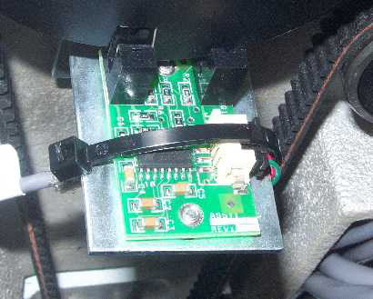
Figure 1 - Connection to Z-Index PCB
6. Cut the cable tie at the z-index PCB that holds the connector in the socket (if tied) and disconnect the z-home lead from the z-index PCB.
|
Figure 3a - EMI Cover |
Figure 3b - New Type EMI Cover |
|
Figure 3c - 33322 Series EMI Cover |
|
7. Remove the EMI cover from the main control board by removing the screws from the edge of the cover. For removal of the 33322 Series EMI Cover refer to Removal of the EMI Cover - 33322 Series.

Figure 4 - Connection to Main PCB (J32)
8. Remove any twist-lock cable ties that bundle the trimmer/z home harness to adjacent harnesses in the base area and disconnect the harness from the Main PCB at location J32 and remove the harness.
9. Connect the lead labeled "TRIMMER HOME" of the replacement harness to the trimmer optical sensor interface cable and push the connectors into the lower arm body. Route the trimmer motor and sensor harnesses into the lower cavity of the lower arm as shown in Figure 5 above.
10. Connect the lead labeled "Z-HOME PCB" to the z-index PCB located right behind the z-index flag.
11. Use small plastic cable ties and tie the connectors snug by attaching the cable tie around the PCB such that the cable tie holds the connector in place. Failure to do this might result in the connectors coming loose which can create difficulties in troubleshooting. (See Figure 1.)
12. Run both leads along the same path as adjacent harnesses and tie them together with twist-lock cable ties and pull the harness through the right lower arm access hole.
13. Connect the harness to the Main PCB at connector location J32 and tie the harness to adjacent ones at 3-4 inch intervals.
14. Carefully install the EMI Cover following the procedures in "EMI Cover - 32232 Series" or "EMI Cover - 32188 Series" as appropriate (see Figures 3a and 3b for pictures of the EMI Covers).
15. Install the covers in the reverse order that you removed them.
16. Turn the machine on.
17. Run a short functional test to ensure both trimmer and z-motors are able to detect their home position.
18. Start the AMAYA OS ( AMAYA OS)
19. Click on the "Maintenance" menu from the AMAYA OS main menu, and then on the "Head Timing" menu tab.
20. Click on the "Z Index" button. If the software detects "Z-index" (same as Z-home) then no related error message will be reported by the AMAYA OS software.
21. Click on the "Steppers" menu tab, and then on the "Home" button under the "Trimmer" column. If the trimmer detects home, then no related error message will be reported by the AMAYA OS software.
22. If you receive no error messages on steps 19 and 20 above, the harness is good.
![]()


