![]()
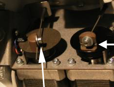
The AMAYA XT and Bravo use a separate motor and push-pull cable to drive the selector and the trimmer knife.
Replacement Parts Required:
Selector Cable
Knife Cable
1. Although not necessary, it will be easier if you remove both of the rear upper and lower arm covers. To do this, remove one of the transparent side covers and the rear screw on the other. Then remove the rear covers.
2. Remove the screws from the needle plate and remove the needle plate.
3. Remove the extrusion cover by loosening the four screws on the side.
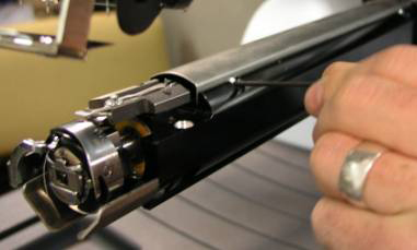
Figure 2: Remove Extrusion Cover
4. Using a small flathead screwdriver, twist the knife hold down clip off of the trimmer assembly.
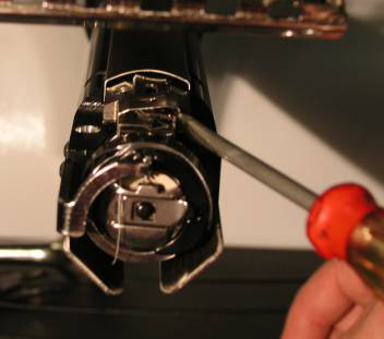
Figure 3: Removal of Knife Hold Down Clip
5. Remove the knife carrier from the trimmer assembly by removing the push-pull cable from the hole in the rear of the carrier and lifting it out.
6. Remove the screw from the left side of the trimmer housing with a 2.5mm Allen wrench.
7. Remove the trimmer housing by taking the push-pull cable out of the hole in the back of the selector.
8. Using a 2.5mm Allen wrench, loosen the screws on the left and right trimmer eccentric.
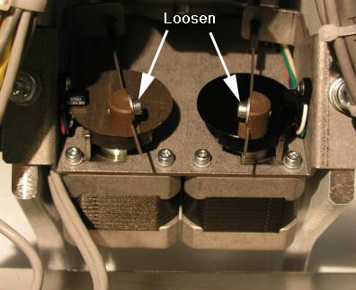
Figure 4: Trimmer Eccentric
9. Pull the knife or the selector cable out of the machine from the front of the extrusion. It is recommended that only one cable be replaced at a time so that the cables are not installed on the wrong side.
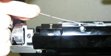
Figure 5: Cable Removal
10. When replacing the cables, be sure they are aligned as they would be in the machine. The knife cable should be pointing UP and the selector cable should be pointing DOWN. If the cables are lined up before they are inserted into the guide tubes, they will not be properly orientated when fully inserted. The cables are difficult to move once inserted.
Figure 6: Proper Cable Alignment
11. Once the cable(s) have been installed, the trimmer must be properly aligned.
12. Insert the trimmer housing into the extrusion. Use the dowel pin on the right side for location.
13. It is critical that the trimmer housing be aligned parallel with the axis of the extrusion. Using the extrusion cover as a guide is a good way to ensure that proper alignment is obtained.
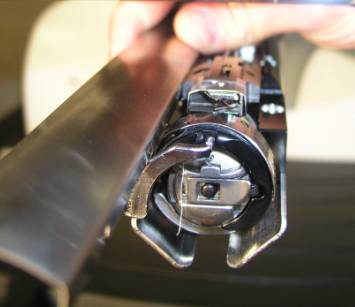
Figure 7: Trimmer Housing Alignment
14. Replace the push-pull cable into the hole in the rear of the selector.
15. Replace the knife in the housing, being sure the push-pull cable is through rear hole in the knife carrier.
16. Replace the knife hold down clip.
17. Before tightening the screws on the eccentric, there are a few steps that must be done.
a. The push-pull cable must be routed through the slot in the cable bracket and behind the washer, as shown below.
Figure 8: Cable Routing
b. When the cables have been routed in the back, finger tighten the screws and be sure the eccentrics are in the home position.
i. The Knife eccentric home position is when the eccentric is fully rotated in the counter-clockwise direction.
ii. The Selector eccentric home position is when the eccentric is fully rotated in the clockwise direction.
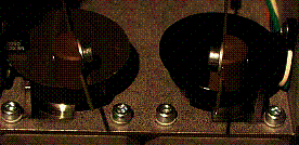
c. Move to the front of the machine and make sure that the tip of both the Knife and the Selector are aligned as shown in Figure 9.
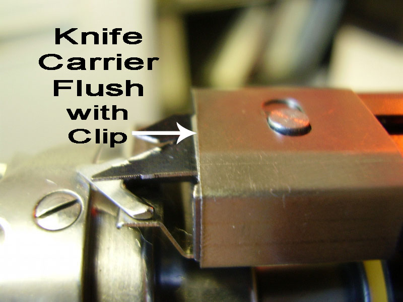
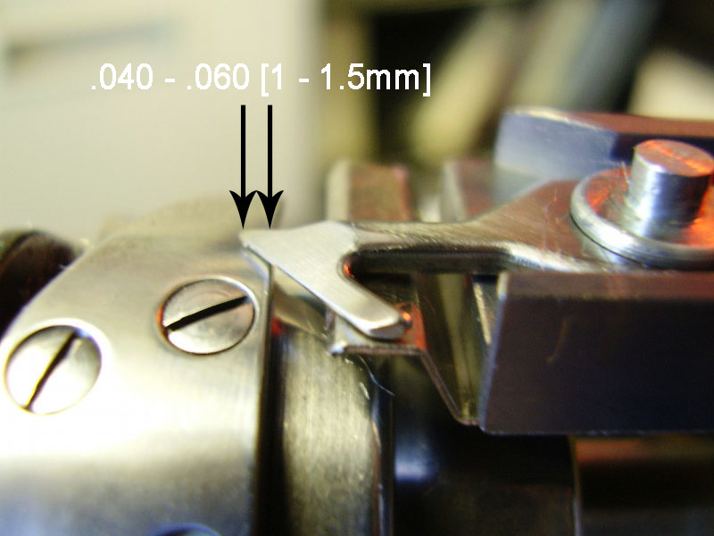
Figure 9: Knife and Selector Positioning
d. Once the Knife and Selector homes have been properly set, the screws on the clamp blocks may be tightened.
18. Install the rear upper and lower arm covers.
19. Install the transparent side cover and the screw in the back of the other one.
20. Install the extrusion cover.
21. Install the needle plate.


