![]()
This procedure can be performed by the machine operator as long as the following procedures are followed explicitly.
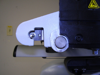
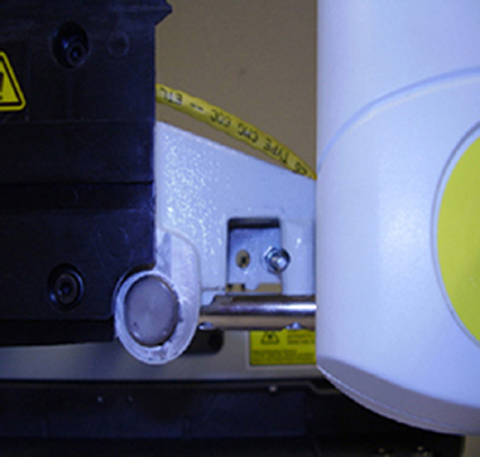
In this procedure you will be measuring the tension of the AMAYA x-cable (see Figure 1).
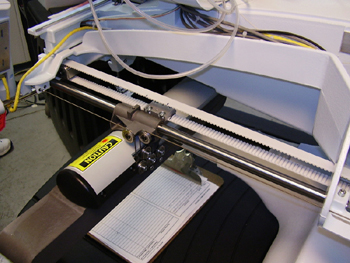
Figure 1 - X-carriage Assembly
This procedure requires the use of a Melco 0-40 lb. Force Gauge, PN 995595-01, and a Universal Force Gauge Adapter, PN 32498.
Attach the Universal Force
Gauge Adapter, PN 32498, to the 0-40 lb. Force Gauge, PN 995595-01
(thread adapter onto the end of the gauge, see Figure 2).
Figure 2- Force Gauge and Adaptor
Turn the machine OFF.
Remove the right arm translucent
arm cover (remove screws with a 3mm hex wrench, see Figure 3).
Figure 3 – Right Arm Cover
Move the x-beam to the position shown in the following image (350mm/13.8" from the center of the X-cable pulley, see Figure 4).
Figure
4 – X-Beam
You can also align the marks on the right y-belt with the edges of the
right y-belt clamp (see Figure 5).
Figure 5 – Right Y-Belt Aligned with Right Y-Belt Clamp
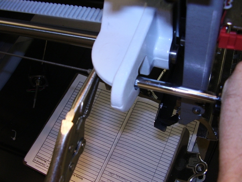
The tension will be measured with the gauge in the midpoint location (see Figure 6).
Figure
6 – Midpoint Location
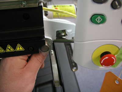
Place the notch of the adapter (with gauge attached) against the x-cable (see Figure 7). If a Breco meter is used, the cable must be plucked at this position.
Figure 7 – X-Cable
Push the force gauge toward the center of the y-guide rail until the x-cable just touches it. The force should read 10.5 ± 0.5 lbs (4.8 ± 0.23 kg). If it does not, proceed to the adjustment procedure.
|
Note: If a BRECO meter is used to measure the tension, the measurement should be 145 +/- 5 Hz. |
Using a 3mm hex wrench, remove both translucent arm covers.
Figures 1
and 2 – Left and Right X-Cable Ends
Using Figures 3 and 4, locate the adjusting nut at each end of the cable. Increase the tension on the x-cable by turning the adjusting nut clockwise. Hold the back end of the stud with a wrench or a pair of pliers to prevent the cable from twisting. Loosen the tension by turning the adjusting nut counterclockwise.
Figures 3 and 4 – Adjusting the Nut
To redistribute the tension in the cable, you must move the x-carriage all the way to the left and then move it all the way to the right. This needs to be done at slow speed in order to prevent damage to the control board. Next, move the x-beam fully forward and fully back.
If it is difficult to adjust the tension to the x-cable using these procedures, it is likely that the cable has stretched out too far. If you are not a Melco service technician, contact Melco Technical Support. Melco service technicians should replace the x-cable following the procedures prescribed in X-Drive Cable Removal and X-Drive Cable Installation.
Check the x-cable tension using the inspection procedure.
When the tension is correct, reinstall the right transparent arm cover and the left front upper arm cover.
NOTE: In AMAYA OS Version 9, Melco has improved needle positional accuracy. This requires that the x-cable tension be within specifications. If it is NOT within specifications there will be an audible resonation indicating that the x-cable is out of tension specification. Please call Melco Technical Support to get instructions on how to set the proper cable tensions.
![]()