![]()
Setting X/Y home requires the use of the Melco X/Y Home Fixture (PN: 30873). The use of this fixture is strongly recommended as it provides for consistent accuracy in the home settings.
Home Adjustment Procedures:
Turn the machine ON.
Engage the emergency stop by pushing ![]() in.
in.
|
|
CAUTION!! Use extreme care not to drop metallic objects, tools, or other conductive material on the Main PCB when you have the base cover removed. If you drop such objects on the Main PCB, it can severely damage the electronics which will be very expensive to repair. |
Remove the base cover.
Remove the EMI cover by carefully removing the screws.
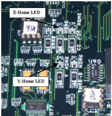
Figure 1 - X- and Y-Home LEDs
Being careful not to touch the main PCB while it is powered up, locate the X and Y-Home LEDs (at locations D37 and D40 respectively). You will need to observe whether these LEDs are on or off while setting home. Home for these LEDs is set correctly right at the point where these LEDs are brightly illuminated (not dim or off).
Remove the left transparent arm cover.
|
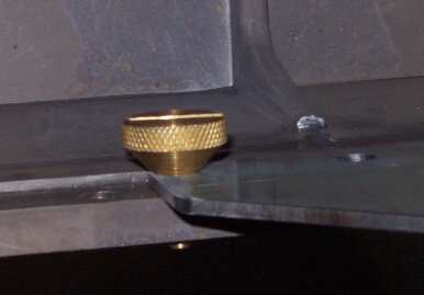
Figure 2 - X/Y-Home Fixture Mounted to X-Carriage |
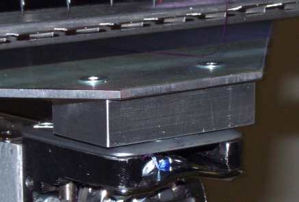
Figure 3 - X/Y-Home Fixture in Needle Plate Hole |
Install the X/Y-home fixture onto the x-carriage at the third screw hole from both ends so that the fixture is centered on the x-carriage as shown in Figure 2 above.
Align the fixture pin over the needle plate hole and push the front of the fixture down until the pin on the bottom of the fixture front block is firmly seated in the needle plate hole as shown in Figure 3 above.
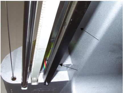
Figure 4 - Y-Home Flag (Bottom View)
Loosen the screws mounting the Y-Home Flag to the bottom of the upper arm body on the left side. The Y-home flag also serves as a wiring channel for the X/Y home harness (the rainbow colored ribbon cable).
Move the Y-Home flag all the way to the front to a dead stop, then slowly move the y-home flag towards the back just until the LED comes on and is brightly illuminated. Tighten the screws to Melco Torque Specifications.
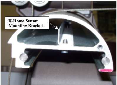
Figure 5 - X-Home Sensor Mounting Bracket
Loosen the two screws that mount the x-home sensor mounting bracket inside the x-beam. Move the mounting bracket all the way to the left end of the beam and then push it back in to the right just until the X-home LED comes on. Tighten the screws back to Melco Torque Specifications.
Move the x-beam all the way to the back to a dead stop, observing the centering of the y-home flag in between the sensors on the X/Y home PCB. Stop if the beam starts to hit one of the sensors. If needed, loosen the screws on the Y-Home flag and center the flag between the optical sensors. Move the x-beam all the way to the front to a dead stop and repeat the procedure at the front. Move the beam back and forth a few times and make sure that the optical sensors on the bottom of the X/Y home PCB do not hit the Y-home flag and the flag is approximately centered on the flag.
|
|
CAUTION!! DO NOT release the E-Stop Button while the Y-Home Fixture is installed on the machine. Severe damage to the machine can occur if you release the E-Stop Button or attempt to operate the machine with the fixture in place. |
Remove the X/Y-home fixture first and then release the emergency stop button by turning ![]() left or right to release it.
left or right to release it.
|
Figure 6a - 32188 Series EMI Cover |
Figure 6b - 32232 Series EMI Cover |
|
Figure 6c - 33322 Series EMI Cover
|
|
14. Install the EMI Cover carefully using the procedures provided in "EMI Cover - 32232 Series", "EMI Cover - 32188 Series", or EMI Cover - 33322 Series as appropriate.
15. Install the base cover.
![]()