![]()
Head Timing Dial Indicator Gauge and gauge pin (PN: 32453-01)
#75 (3mm) hex driver or equivalent bent Allen wrench
3lb weight
XT Head Timing Adaptor (PN: 33065)
The Z-flag is manually adjusted such that a Bottom Center command initiated either by the keypad or software will generate the lowest possible mechanical position of a corresponding needle at 180 ° +/-0.5 ° z-axis position (displayed in the AMAYA Operating System (OS) Maintenance > Head Timing” menu).
Color change to needle #9.

Figure 1 - AMAYA OS – Maintenance/Head Timing Menu
Open the Maintenance Menu, then click the Head Timing tab.
Remove the bobbin case and the needle plate.
Assemble the XT Head Timing Adaptor (PN: 33065) to the dial indicator (PN: 32453-01) as shown in Figure 2.
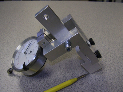
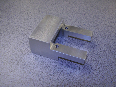
Figure 2 - Adaptor and Dial Indicator
Install the dial indicator (PN: 32453-01) and XT Head Timing Adaptor (PN: 33065) on the lower arm extrusion as shown in Figure 3. Tighten the screws enough to hold the fixture securely.

Figure 3 - Dial Indicator and Adaptor Installed on Lower Arm Extrusion
Cycle the machine to its Bottom Center position by pressing the Adjustment (![]() )and Arrow Down (
)and Arrow Down (![]() )keys simultaneously on the keypad (be careful not to let the needle “slam” against the indicator plunger because this may cause damage).
)keys simultaneously on the keypad (be careful not to let the needle “slam” against the indicator plunger because this may cause damage).
With the indicator plunger in full contact with the needle, hang the 3 lb weight from the needle clamp as shown in Figure 4. Be sure its path is unrestricted and not touching the plunger.
NOTE: The weight must be attached before needle depth.
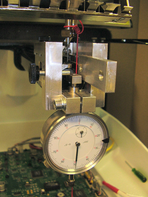
Figure 4 - Needle Clamp and Weight
Decrease the angular position by at least 0.004” from the bottom dead center position using the Hoop ![]() command.
command.
Using the micro-stepping command (Trace (![]() ) and Arrow Down (
) and Arrow Down (![]() ) keys), increase the angular position until the dial indicator needle stops moving (= “Z Lower Dwell Start”). Continue to increase in angular position; all the while there should be no movement through 179.5
°
- 180.5
°
.
) keys), increase the angular position until the dial indicator needle stops moving (= “Z Lower Dwell Start”). Continue to increase in angular position; all the while there should be no movement through 179.5
°
- 180.5
°
.
Increase the angular position to the point where the needle starts to rise (= “Z Lower Dwell Stop”).
Continue to increase the angular position until 0.001” rise (= “Z 0.001” Rise”) is measured. The corresponding angular position at this point should be 182.5+/- 0.5 ° . If not, z-timing has to be reset.
Color change to needle #9.
Open the Maintenance Menu, then click the Head Timing tab.
Figure 3 - Turn Z-Axis Flag Counter-Clockwise (CCW)
At the rear of the machine, loosen the z-axis flag; and while facing the z-axis flag, rotate it completely counter-clockwise and re-tighten it. See Figure 3.
|
|
Note: If the machine loses power after this step, it will be necessary to “roughly” reset z-timing. Do so by following the steps outlined below. Otherwise, proceed to step 12. |
Shut the machine off.
Engage the E-Stop button (![]() ) on the user interface.
) on the user interface.
Turn the machine on and let the system (machine and software) boot up.
Manually move the z-axis to its upper most position (upper dead center).
Loosen the z-flag at the back of the machine.
Rotate the z-flag back and forth to the point where the Z-Index LED is triggered.
Tighten the z-flag at this transition point.
Reboot the machine.
Cycle the machine to Head-Up at least three times by pressing the Adjustment (![]() ) and Arrow Up (
) and Arrow Up (![]() )keys simultaneously on the keypad.
)keys simultaneously on the keypad.
NOTE: Weight must be attached before needle depth.
Install the dial indicator (PN: 32453-01) with the adaptor (PN: 33065) on the lower arm extrusion as shown in Figure 4. Tighten the screws enough to hold the fixture securely.
Figure 4 - Dial Indicator Installed on Needle Plate Bracket
Cycle the machine to its Bottom Center position by pressing the Adjustment (![]() ) and Arrow Down (
) and Arrow Down (![]() )keys simultaneously on the keypad. (Be careful not to let the needle “slam” against the indicator plunger because this may cause damage).
)keys simultaneously on the keypad. (Be careful not to let the needle “slam” against the indicator plunger because this may cause damage).
With the indicator plunger in full contact with the needle, hang the 3 lb weight from the needle clamp as shown in Figure 4 above. Be sure its path is unrestricted and not touching the plunger.
In the Head Timing window, go to Needle Depth (bottom center) Release Z and manually rotate the z-shaft back and forth as necessary to approximately locate the lowest mechanical position on the dial indicator. The needle will be at it’s lowest point right before it begins to rise.
Use the micro-step command on the keypad to decrease (press the Trace key (![]() ) and the Arrow Down key (
) and the Arrow Down key (![]() )) the angular position until the needle begins to rise and continue doing so for 0.003” more.
)) the angular position until the needle begins to rise and continue doing so for 0.003” more.
Using the micro-step command on the keypad, increase (press the Trace key (![]() ) and the Arrow Up key (
) and the Arrow Up key (![]() ) the angular position back to the lowest needle position. After the needle stops moving, note the angular position and continue to micro-step in the same direction for at least 1.5
°
more; the needle should not move.
) the angular position back to the lowest needle position. After the needle stops moving, note the angular position and continue to micro-step in the same direction for at least 1.5
°
more; the needle should not move.
Verify that the dial indicator is zeroed. If it is not on zero, reset the dial indicator to zero.
Increase the angular position by micro-stepping until the dial indicator registers a needle bar rise of 0.001”. Record the angular readout at this height and include all decimal places (![]() ).
).
Important: Add 177.5
°
to the angle from the previous step (![]() +177.5) =
+177.5) = ![]() setting (include all decimal places). The sum should not be greater than 360
°
! If it is, then make sure the z-flag was rotated fully counter-clockwise. If it wasn’t, repeat the procedure from step 15 forward.
setting (include all decimal places). The sum should not be greater than 360
°
! If it is, then make sure the z-flag was rotated fully counter-clockwise. If it wasn’t, repeat the procedure from step 15 forward.
Using the Step Forward command in the Head Timing tab, increase the angular position by 2
°
increments until the gauge pin clears the dial indicator plunger. After that, support the weight step upward in 5
°
increments or more; stopping roughly 5
°
-7
°
before reaching the ![]() setting position.
setting position.
At this position, let the weight once again hang freely and use the micro-step command to slowly increase angular position to exactly ![]() setting (Note: It is very important that you don’t overshoot this value. If this happens, rotate back at least 5
°
before this point and repeat.)
setting (Note: It is very important that you don’t overshoot this value. If this happens, rotate back at least 5
°
before this point and repeat.)
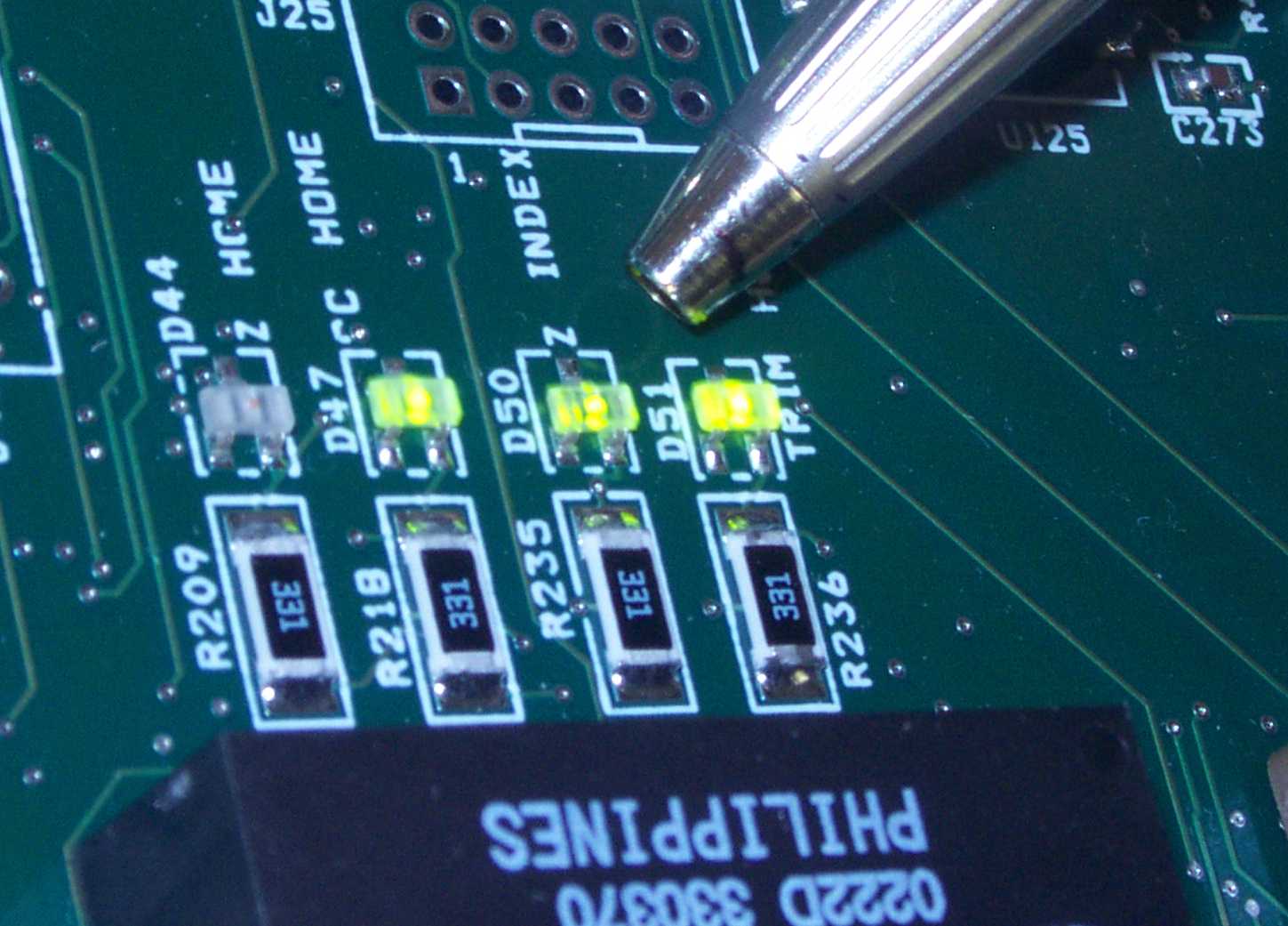
Figure 5 - Z-Index LED (Location D50)
Loosen the z-flag and manually rotate it until the z-index LED (located at D50 on the main PCB as shown in Figure 5 above) changes state. Carefully tighten the flag in place at this transition point with the LED light off.
|
|
(Note: It is very important that the z-flag is set at a z-shaft angle equal to |
The LED must turn off/on at +/- 0.2
°
of ![]() setting. Use the micro-step command to rotate the z-shaft down in angular position by at least 2
°
, then forward again and note the angular position at which the z-index LED changes state. Again, this should be within +/- 0.2
°
of
setting. Use the micro-step command to rotate the z-shaft down in angular position by at least 2
°
, then forward again and note the angular position at which the z-index LED changes state. Again, this should be within +/- 0.2
°
of ![]() setting.
setting.
Remove the weight and cycle the machine to Head-Up at least 3 consecutive times (be sure the needle in the needle bar clears the dial indicator plunger during this step).
Cycle the machine to its Bottom Center position and replace the weight. (Be careful not to let the gauge pin “slam” against the indicator plunger because this may cause damage).
Decrease the angular position by at least 0.004” from this position.
Increase the angular position to the point where the needle starts to rise (= “Z Lower Dwell Stop”).
Continue to increase the angular position until 0.001” rise (= “Z 0.001” Rise”) is measured. The corresponding angular position at this point should be 182.5+/- 0.5 ° . If not, repeat the procedure from the beginning.
The purpose of this setting is to record the angular position necessary to achieve 0.090” rise from the Bottom Center position. This position will be used for hook timing.
With the weight and dial indicator still in place from the previous step above (0.001” rise), increase the angular position (use 1º steps and the micro-stepping command) until 0.090” rise (= “Z 0.090” Rise”) is measured. Be careful not to overshoot! Record the corresponding angular position (all decimals).
Remove the weight and cycle the machine to Head-Up at least 3 consecutive times (be sure the needle in the needle bar clears the dial indicator plunger during this step).
Cycle the machine to its Bottom Center position and replace the weight. (Be careful not to let the needle “slam” against the indicator plunger because this may cause damage)
Increase the angular position (use 1º steps and the micro-stepping command) until 0.090” rise is measured. Record the corresponding angular position. It should be within +/-0.5 ° of the position recorded in step 20.
Record the angular position number in the machine chassis (note all decimals!), crossing the previous number out using a permanent marker or use tape to cover the previous number and record the new number on the tape.
![]()