![]()
The grabber blade will need to be replaced if it is damaged due to a machine or operator error. It should be replaced anytime the blade is nicked, bent or damaged in any manner. Damage to the grabber blade usually occurs because the path of the grabber blade is obstructed, the grabber assembly is not properly adjusted, or the screws are loosened or not properly torqued.
Parts Needed for Repair:
Grabber Blade
Four M3x6mm flat head slotted screws
Figure 1 - Grabber Blade (bottom view)
1. Remove the four M3x6mm flat head screws on the bottom of the grabber blade and throw them away. It is recommended that you do not reuse the screws.
2. Apply red loctite (MS222) on the screw threads and install the replacement grabber blade in position, starting all four screws loose. Tighten them to Melco Torque Specifications when all of the screws are started.
3. Loosen the four M3x6mm button head screws on the back of the lower trap assembly.
4. With the machine tuned off, move the grabber blade by hand between the upper and lower trap assemblies and check the horizontal and vertical alignment.
NOTE: Rotate the grabber home flag on the back of the needlecase if the grabber blade cannot be moved by hand.
5. If the grabber blade is aligned between the two trap assemblies, then proceed to step 7. Otherwise adjust the grabber blade to the upper trap assembly using the following procedures.
a. Move the grabber blade back out from the upper and lower trap assembly.
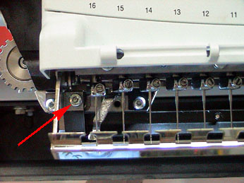
Figure 2 - Upper Trap Assembly Front Screw
b. Loosen the front M4x6mm cap head socket screw mounting the upper trap assembly to the needlecase.
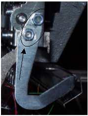
Figure 3 - Upper Trap Assembly Hex Nut
c. Loosen the two M4 hex nuts located at the bottom of the right side of the needlecase.
d. Move the grabber blade back in between the upper and lower trap assemblies.
e. Tighten the front screw mounting the upper trap arm to the front of the needlecase to Melco Torque Specifications.
f. Tighten the two M4 hex nuts on the bottom right side of the needlecase to Melco Torque Specifications. Make sure the grabber blade is engaged evenly from needle 1 to needle 16 before tightening down the nut.
g. Tighten the four M3x6mm button head screws that mount the lower trap assembly to the upper trap assembly to Melco Torque Specifications.
h. Move the grabber blade back out of the needle case to it's full extended position.
i. Move the grabber blade in and out of the upper and lower trap assembly several times. It should just brush against the grabber trap velcro on the upper trap and be parallel all the way across.
j. Visually check the position of the grabber blade at the fully extended position. A vertical line extending down from the inside edge of the grabber blade should be 9.9mm±0.3mm from a vertical line extending down the front of the nearest needle bar. If this adjustment is not correct, contact Melco Technical Support for instructions.

Figure 4 - "Steppers" Submenu
7. Open the "Maintenance" menu in the AMAYA software and click on the "Steppers" menu tab. Under the "Grabber" column, click on the "Step>" button and manually run the grabber through it's cycle. Observe any rubbing of the grabber blade and look for other parts that might be out of adjustment and hitting the grabber blade. Contact Melco Technical Support if other adjustments are required beyond the instructions provided for in this Manual.
8. If there is no obstruction or interference noticed when stepping the grabber through it's normal cycle, press "Start Test" to test the grabber (located under the "Grabber" column) and let the grabber test run for a few minutes. If the grabber fails to function correctly during the test, make adjustments as necessary. To end the grabber test, click on "End Test" under the Grabber column.
9. Run the "Trim Test" sew design "AMTRIM01A.exp" on the machine and watch for long tails and pullouts. If you have long tails and pullouts on the test design, you need to tighten up the adjustment slightly. Turn the machine off and repeat all the steps from Step 4 forward and tighten the adjustment of the grabber blade against the upper trap velcro.
![]()