![]()
|
|
This repair requires timing and other adjustments and should be done only by a Melco authorized service technician. |
The only two reasons to remove the x-beam assembly for repair would be if the two steel rails inside the x-beam are damaged because of fretting corrosion due to improper adjustment or lack of lubrication.
Replacement Parts Needed:
(Only if defective - replace them where indicated in the below procedures.)
X-Beam w/Rails Assembly
Replacement/Repair Procedures:
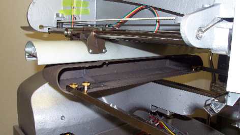
Figure 1 - X-Beam and Carriage Installed on Machine
1. Color change to Needle #16.
2. Turn the machine OFF.
3. If the machine has a hoop installed, remove it from the machine.
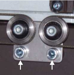
Figure 2 - Cable Bracket Removal
4. Remove the two screws holding the cable bracket on the rear of the x-carriage.
5. Remove the cap on either side of the beam and slide the x-carriage out of the beam.
6. Disconnect the x-home sensor optical switch harness from the X/Y home PCB.
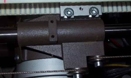
Figure 3 - Bearing Block Assembly Installed on Machine
7. Remove the 3 screws mounting each of the two bearing block assemblies to the top of the x-beam and remove the beam.
8. Apply red loctite (MS222) to the threads of the button head socket screws and reinstall the x-beam assembly to the bearing block assemblies. Tighten the button head socket screws to Melco Torque Specifications.
9. Remove the x-home optical switch mounting bracket with the sensor mounted from the old beam and install it in the replacement beam using the installation procedures prescribed in "X-Home Optical Switch Assembly Replacement".
10. Install the end caps on both ends of the x-beam assembly.
11. If you do not have any further work on the machine, reinstall all of the covers in the reverse order that you removed them from the machine.
![]()