![]()
|
|
This repair requires timing and other adjustments and should be performed by a Melco authorized service technician. |
The X-home PCB needs to be replaced when the sensors fail to detect home. This condition normally results when the optical sensors are damaged due to mechanical interferences or incorrect adjustment. Optical sensors should be cleaned only with compressed air. The use of any kind of solvent or cleaning liquid will damage the sensors.
Optical sensors might also be damaged through improper torque of the mounting screws, misalignment of the PCB, or X & Y home flags.
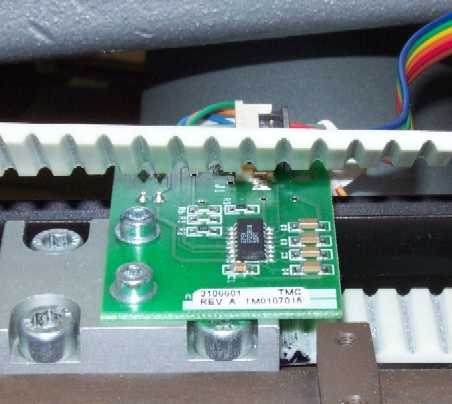
Figure 1 - X/Y Home PCB (Belt turned up for illustration)
|
|
WARNING!! A small risk exists of unpredictable movement of internal parts when the optical sensors are disconnected. This creates a risk of personal injury if parts suddenly move. Always turn off the machine before disconnecting optical sensors. |
Replacement Parts Needed:
X/Y Home PCB
1. Turn the machine OFF.
2. Make contact with a metal part of the machine to dissipate any static build up in your body.
|
|
CAUTION!! Use extreme care not to drop metallic objects, tools, or other conductive material on the Main PCB when you have the base cover removed. If you drop such objects on the Main PCB, it can severely damaged the electronics which will be very expensive to repair. |
3. Remove the base cover, the left transparent arm cover and the back screw from the right transparent arm cover, the upper arm back cover, and the lower arm rear cover.
4. Use a pencil and trace the outline of the X/Y Home PCB on the top of the Y-drive timing belt clamp.
5. Disconnect the harnesses from the PCB connectors and set the harnesses off to the side of where they were disconnected from. Do not get these two harnesses mixed up with each other. Mark them with tape to prevent confusion between the two harnesses.
6. Loosen and remove the two M3x6mm cap head socket screws and M3 flat washers.
7. Remove the X/Y Home PCB and replace it with a new one.
8. Align the replacement PCB to the marks you traced on the Y-drive timing belt clamp.
9. Tighten the screws just enough to hold the PCB securely. Examine the position of the y-home flag between the optical sensors and make sure that the flag is centered and does not hit the sensors. If adjustment is needed, loosen the PCB and move it one way or the other to center the flag and tighten the screws just enough to secure the PCB and recheck the position of the flag again.
10. Tighten the screws to the minimum Melco Torque Specification (10% less than specified for the screws).
11. Turn the machine ON.
12. Install any size hoop with one piece of backing.
13. Select the appropriate size hoop in the AMAYA OS ( AMAYA OS).
14. Measure and mark the center of the hoop by measuring from the left and right and front to back inside border of the hoop. Place an "X" mark on the center location on the backing.
15. Click on the "Commands" menu in the AMAYA OS main menu, and then on the "Set Home" and then center the hoop.
16. Click on "Maintenance" menu in the AMAYA OS main menu, on the "Head Timing" menu, and then on the "Bottom Center" button.
17. If the needle is off front to back, adjust the X/Y Home PCB from Step 8, moving it in the direction and distance that the needle is off center front to back and tighten the screws to Melco Torque Specifications.
18 Reinstall the covers you removed in step 3.
![]()