![]()
The advanced troubleshooting procedures explained in this section are intended for a more detailed analysis of the condition and/or failure of stepper motors. These procedures are more detailed and should be used when the regular troubleshooting procedures prescribed for each individual motor fail to yield satisfactory data. They should also be used in case more extensive testing is desired or required, especially if a mechanical bind or alignment issue is suspected of preventing the regular test procedure from being used.
Prior to beginning the advanced troubleshooting of stepper motors and a particular motor being analyzed, the AMAYA must be at a certain status before beginning the test, as indicated below.
|
Motor Being Tested |
AMAYA Status Requirement |
|
Grabber Motor |
The z-shaft must be at the head up position. |
|
Selector |
The z-shaft must be at the head up position. |
|
Trimmer Knife |
The z-shaft must be at the head up position. |
|
Color Change |
The thread feed must be at its home position and the z-shaft must be at the "Head Up" position. |
|
Thread Feed |
The thread feeder lever of the current needle must be up with the machine at "Head Up" |
You also need to locate the LEDs that indicate the status of the individual stepper motor. The location numbers are indicated below. You will generally find the indicator LEDs located by the respective stepper motor harness connection. When you are referred to the stepper motor phase indicator LEDs, you will need to watch the state (red, green or off) of these LEDs.
|
|
WARNING!! Always make sure that you keep away from moving parts on the machine and do not touch electronic parts when powered on. Handle electronic parts carefully to avoid causing any damage to them. |
Locate the LEDs with the machine being turned off before you begin the test so you are not tempted to run the test with your head close to the board or moving parts in the trimmer system, rotary hooks, or the needlecase assembly.
|
Motor |
Phase Indicator LED Locations |
|
Grabber Motor |
D59 and D60 |
|
Selector |
D63 and D64 |
|
Trimmer Knife |
D63 and D64 |
|
Color Change |
D61 and D62 |
|
Thread Feed |
D57 and D58 |
The phase indicator LEDs will alternate between eight states: red-green, off-green, green-green, green-off, green-red, off-red, red-red, and red-off. (The colors are in order as if you viewed them from the left side of the Main PCB. If you view the colors from the right side of the main PCB, the states will be reversed.) You do not need to know what each state means, just that the sequence is there which indicates the motor has moved through a complete cycle.
Test Procedures:
1. Turn the machine OFF.
2. Remove the base cover.
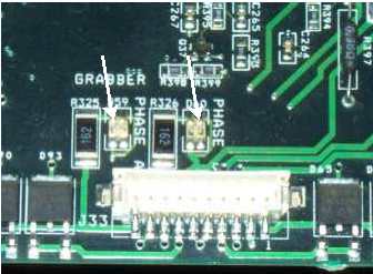
Figure 1 - Grabber Phase Indicator LEDs
3. Find the stepper motor indicator LEDs. They will generally be in the vicinity of the respective stepper motor harness connector.
4. Turn the machine ON and keep hands, hair, loose clothing and jewelry away from moving parts and the main PCB.

Figure 2 - AMAYA OS Steppers Menu
5. Load the AMAYA OS ( AMAYA OS), then click on the "Maintenance" menu from the AMAYA OS main menu screen and select the "Steppers" tab.
6. Each stepper motor has a set of command buttons under their respective heading. Find the column pertaining to the stepper motor. You will be working with these command buttons when they are referenced in this procedure.
7. Ensure the stepper motor that you are testing is in the correct state and then click on the "Step>" command button. As you click the step button, write down the state of the respective phase indicator LEDs (red, green, or off). For this test, step the motor in one direction only through several complete cycles. After you have clicked the stepper button eight times in the same direction, the sequence you started off with will return. (Please note that if you are testing the color change stepper motor, you will only need to click the stepper motor button four times). Check to see if the LED's are at the same intensity. If not, disconnect the motor. The LEDs should now be bright. If the LEDs are not bright, try replacing the motor. If this does not fix the problem, replace the main PCB. When doing the LED test if either LED never lights, or only one color lights (red or green only), unplug the motor from the harness and see if the LEDs change. If they do not, you can assume the main PCB is defective and needs replacing.
8. In addition to watching the LEDs as you step the motor through a cycle, observe its mechanical performance. Look for some kind of mechanical bind or other defect that interferes with the performance and then fix any that you find.
9. If the machine cycles through all eight phase states, both the software and the firmware (main PCB) are in good condition. Look for mechanical issues if the stepper motor is still not working correctly. Software bugs are possible, but at this point, the issue will probably be a mechanical bind, or a failure in the stepper motor itself.
![]()