1. Verify that a compatible version of AOS is installed on the customer’s computer. If not, install the latest version from the upgrade kit.
2. Turn OFF the machine and close AMAYA OS.
3. Remove the Needle Plate, Rear Cover, and Front and Rear Extrusion Covers from the Lower Arm.
4. Remove the Base Cover and EMI Shield to access the Control PCB. If the Control PCB is a -16M, replace it with the -18M Control PCB and related harnesses in the installation kit (refer to Technical Manual for replacement). If the machine has a Multi-Plex PCB on the Trimmer Drive Assembly, remove it and replace the harnesses with the ones in the installation kit.
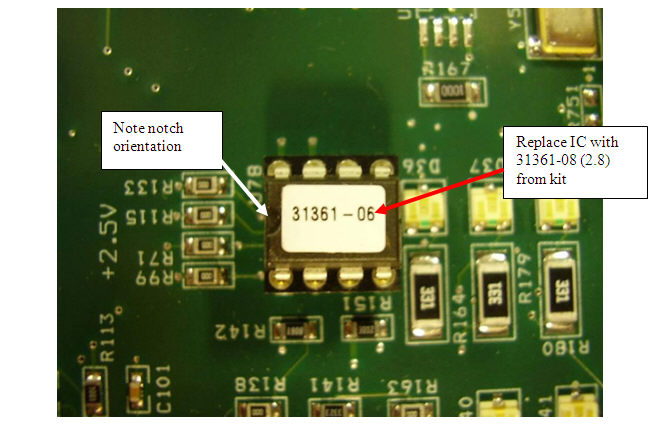
5. Verify if the Programmed IC at location U78 on the Control PCB is labeled as P/N 31361-08 (or 2.8). If not, replace it with the Programmed IC from the installation kit. Verify proper chip orientation by noting the notch during replacement (see below).
6. Re-assemble the EMI Shield and Base Cover.
7. Open AMAYA OS and go to Tools, Options, Ethernet and make sure Force Download is ON.
8. Turn ON the machine. In AMAYA OS, Go to Tools, Maintenance, Steppers, Set XT Trimmer Type, and set to 2.

9. Engage the Emergency Stop button!
10. Remove the XT Trimmer Drive Assembly, P/N 32898, and XT Trimmer Assembly, P/N 32958.
11. Remove the XT Knife and Selector Push-Pull Cables and Housings and discard.
Note: The new Push-Pull Cables for the ACA Trimmer are the same for both the Knife and Selector.
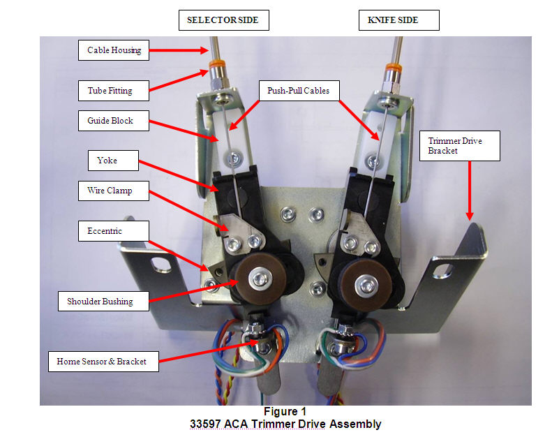
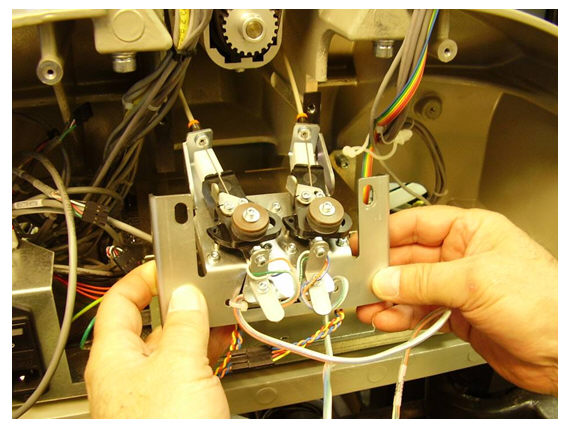
12. Reference the new ACA Trimmer Drive Assembly, P/N 33597, shown below. Install the new Push-Pull Cables and Housings into the Tube Fittings. Make sure they are fully and securely seated into the Tube Fittings. Slide the Push-Pull Cables through the slot in the Yoke and under the Wire Clamps.
Note: Do not tighten the Wire Clamp screws. The cables must move freely under the Wire Clamps. The wire clamp screws will be tightened later in this procedure.
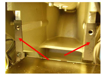
13. Remove the adhesive backing from the Dampening Gaskets, P/N 33637, and stick them to the mounting surfaces of the Lower Arm as shown below.
14. Install the ACA Trimmer Drive Assembly into the back of the Lower Arm. Raise the mounting bracket to its highest position and lightly tighten the M6 mounting screws. Note: If M6 Flat Washers are not already present, install them between the Bracket and the M6 Lock Washers.
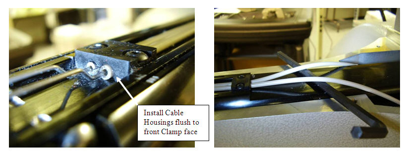
15. Install the front Cable Clamp over the Cable Housings so they are flush to the front face and tighten the screws as shown below. Next, pull the Cable Housings tight and flat against the Lower Arm Extrusion and install the rear Cable Clamp. Note: Placing an M5 Allen Wrench under the Cable Housings as shown below helps keep them tight while installing the rear clamp.
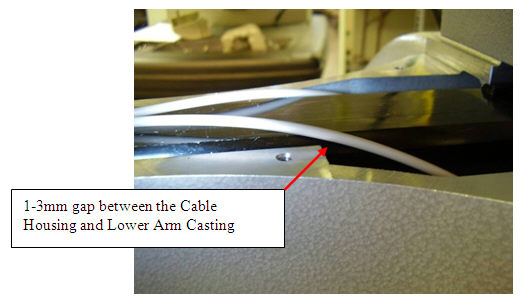
16. Remove the M5 Allen wrench if used in previous step and adjust the height of the Trimmer Drive Bracket so the Cable Housings clear the Lower Arm Casting by 1-3mm as shown below. Tighten the M6 mounting bracket screws to 23in-lbs.
17. Verify that the E-stop is still engaged and connect the respective Knife and Selector Motor and Home Sensor Harnesses. Reference Figure 1 for Selector and Knife cable harness identification.
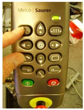
18. Release the E-stop button. Press the “Trace” and “Adjust” buttons at the same time as shown below (Trimmer Clean Function). Verify both motors have moved from home position. This command moves the ACA Trimmer to the fully extended position. Next, press any key on the User Interface and the ACA Trimmer will retract to its home position.
NOTE: If only one motor rotates, select the Detect Trimmer button in the Tools, Maintenance, Steppers menu and repeat this step.
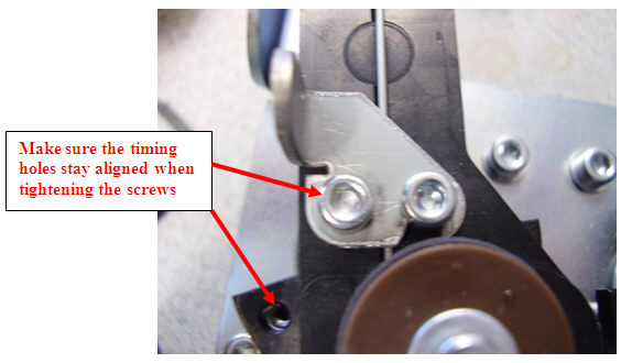
19. Adjust each Home Sensor Bracket in or out until the timing hole in the Eccentric aligns with timing standoff in the Trimmer Drive Bracket as shown below. Each time an adjustment is made to the Home Sensor Brackets, perform a Trimmer Clean to verify if the timing holes are aligned.

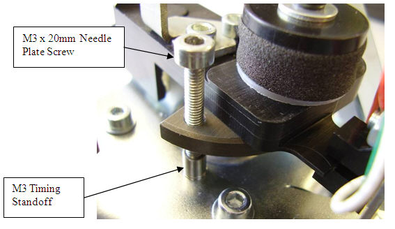
20. Using an M3 x 20mm screw (Needle Plate mounting screw), verify that it freely threads into the M3 timing standoff as shown below. Once the alignment is correct, fully tighten the Home Sensor Bracket screws and remove the M3 Needle Plate screw. Check the timing hole alignments (Trimmer Clean) one last time after tightening the sensor mounting bracket screws.
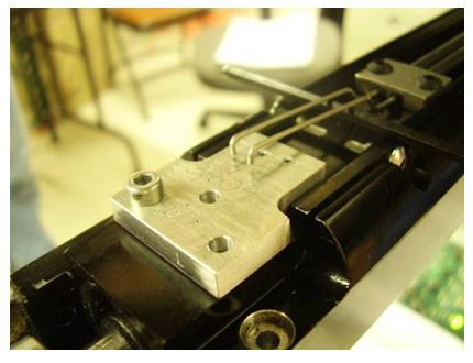
21. Install the ACA Trimmer Home Fixture, P/N 33539, lightly tighten the M3 screw and position the Push-Pull Cables in their respective holes as shown below.
22. Tighten the M3 screws on both the Knife and Selector Wire clamps as shown below.
23. Remove the Push-Pull Cables from the fixture and perform a Trimmer Clean. Note: Place an Allen wrench under the Push-Pull Cables as shown below to hold them above the fixture during the Trimmer Clean. Take care not to bend the Push-Pull Cables.
24. Confirm that the cables drop back freely into the holes of the fixture. If either Push-Pull Cable does not align in its respective fixture hole, loosen the Wire Clamp screws, place the Push-Pull Cables back in the fixture holes and repeat steps 21-24.
25. Remove the Trimmer Home Fixture.
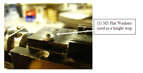
26. Locate the 3mm diameter dowel pin at the front of the Lower Arm Extrusion. Stack (3) M3 flat washers over the dowel pin to act as a height stop (see below) and tap it down with a small hammer.
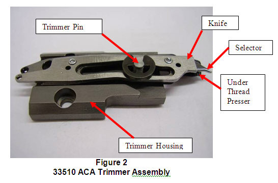
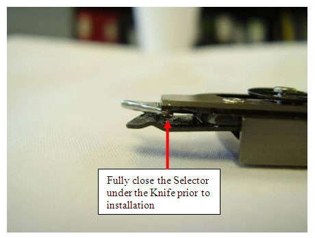
27. Reference Figure 2 below for part identification within the ACA Trimmer Assembly, P/N 33510. Push the Selector to the fully closed position as shown in the second picture below.
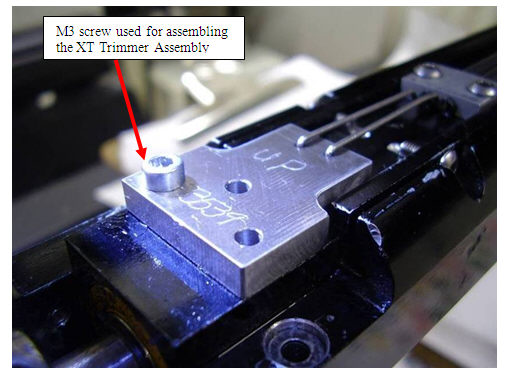
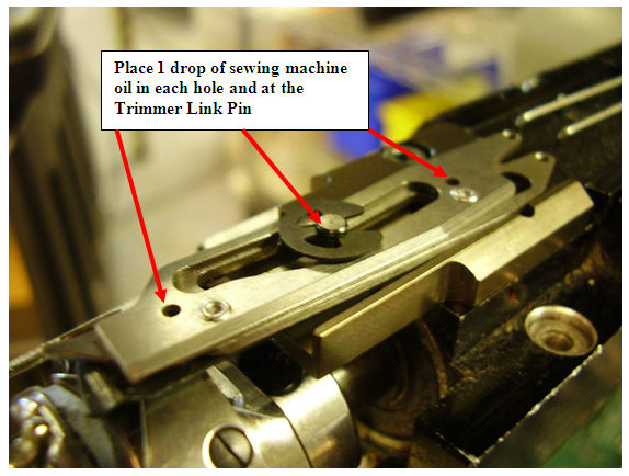
28. Install the ACA Trimmer Assembly onto the Lower Arm Extrusion. Rotate the Trimmer Housing left until it stops and tighten the M3 mounting screw. Oil the assembly at the points indicated below.
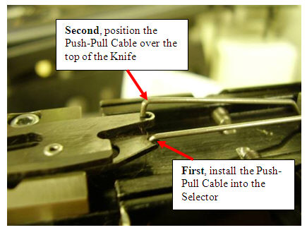
29. Install the Push-Pull Cables. First, install the Push-Pull Cable into the Selector. Second, position the other Push-Pull Cable on top of the Knife as shown below. It should be slightly forward of the hole.
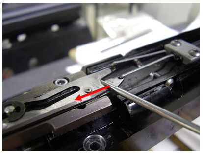
30. Using the blade of a small screw driver or other tool, push the back of the Knife forward until the Push-Pull Cable engages completely into the Knife hole as shown below.
31. Place one M3 Flat Washer in each hole where the Needle Plate mounts on the Lower Arm Extrusion as shown below. This positions the Needle Plate a little higher to prevent interference with the ACA Trimmer. Note: If you notice the ACA Trimmer rubbing on the underside of the Needle Plate during operation, place an additional M3 Flat Washer in each hole.
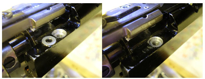
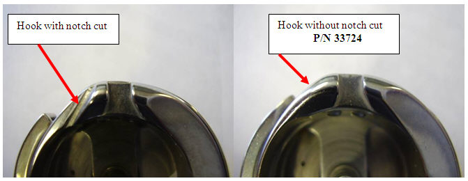
32. Visually inspect the Rotary Hook currently on the machine to determine if changing the hook is required. The correct Rotary Hook, P/N 33724, does not have a notch cut as shown in the pictures below. If the current Rotary Hook has a notch cut, replace it with P/N 33724.
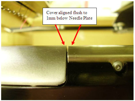
33. Re-assemble all covers. Note: Assemble the Front Extrusion Cover so that it’s flush to 1mm below the top of the Needle Plate as shown below.
34. Load AMTRIM and test sew this design 2 times with zero trimmer defects to confirm that the ACA Trimmer is functioning properly. Note: The trimmed thread tail lengths under the embroidered garment are longer with the ACA Trimmer (13mm) versus the XT Trimmer system (4mm).