![]()
To test power supplies that are already installed in the machine, use the following procedures:
1. Check the 5V LED at location D43 and the 15VLED at location D32 on the main PCB. Both of them should always be illuminated when the machine is turned on.
2. Check the status of LEDs at locations D52, D53, and D45. They should be blinking.
3. If any of the LEDs are not correct (on or blinking as appropriate) as described in steps 1 and 2 above, turn the machine OFF, remove the lower arm rear cover, disconnect the 36V power harness from the main PCB.
4. Use a voltage meter set to measure DC voltage and measure the voltage output on the 36V power harness. Place the ground lead from the voltage meter on the pin to any of the black wires and the positive (hot) lead from the voltage meters on any one of the red wires. Turn the machine ON and check the voltage which should be between 34.5V to 38V DC.
5. If the voltage input measured from any of the red wires in the 36V power harness is not between 34.5V to 38V DC, wriggle the cable and look for voltage change.

Figure 1 - Power Supply Voltage Measurement Points
(wires disconnected for illustration only)
6. If the voltage changes, measure 36V DC output at the power supply terminal block. If the power output is stable and measures between 34.5V to 38V DC, then the 36V power harness is probably bad. Replace the harness and if it does not solve the problem, proceed with testing the power supply unit. Otherwise, reinstall the covers and tighten the screws to Melco Torque Specifications.
Check the power supply unit itself:
7. Turn the machine off.
8. Disconnect the A/C wallpower supply harness from the main power input connector. Disconnect the external Ethernet cable.
9. Remove the power supply assembly from the machine following the procedures for removing the power supply in the section titled "Power Supply Assembly".
10. Set the power supply on a table or work bench with an A/C outlet close by.

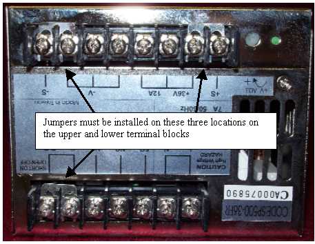
Figure 2 - Power Supply Unit Terminal Jumpers
11. Check and make sure that the jumpers are installed as shown in the picture above. If the terminals are missing, either order replacement jumpers, or you can fabricate replacement jumpers with 16 gauge AWG wire and ring connectors available from any electrical supply store. Replace any missing jumpers
12. Connect an AC power cord into the power entry module on the power switch bracket located on the back of the power supply assembly.
13. Turn the power switch on.

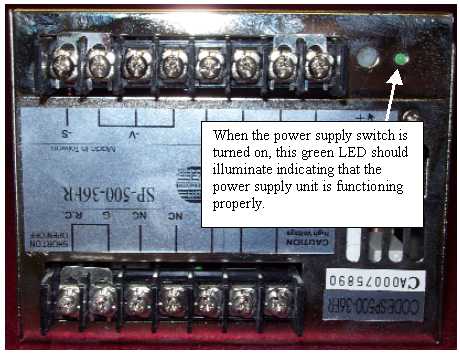
Figure 3 - Power Supply Indicator LED
14. The green LED located on the top right side of the back of the power supply unit should immediately illuminate.
a. If the green LED is not illuminated, measure the A/C input voltage at the location shown in Figure 1 above. You should be getting 110V or 220V AC ±10% depending on the wallpower supply. If you have no or low power input at these two terminals, replace the fuse.
b. If the fuse is good, but you still have no AC input, verify that the wallpower supply outlet is supplying sufficient power to the machine.
c. If correct power is being supplied to the machine, and the fuse is good, but the power input is still too low or none, replace the power supply assembly.
d. If the power input is correct, and the green LED does not illuminate, replace the power supply assembly. (This indicates that the power supply unit itself has failed.)
15. Use a voltage meter set to measure DC output and measure the voltage output on the upper terminal block, measuring at the middle terminals as shown in Figure 1.
a. The black (common) electrode of the voltage meter goes on the ground (black wire) terminal, and the red (positive or hot) electrode of the voltage meter goes on the positive (red wire) terminal.
b. Measure the DC output voltages. The range should be between 34.5 to 38 DC volts. If the voltages are not in this range, then replace the power supply assembly.
16. If the green LED on the side of the power supply unit is illuminated and the 36V DC output is between 34.5 to 38V DC then the power supply assembly is good. Follow the power supply installation procedures entitled "Power Supply Assembly" to install the Power Supply Assembly into the machine.
17. If none of the above indicates a failure, the power supply assembly is good and can be installed in the machine using the procedures for installing the power supply assembly in the section titled "Power Supply Assembly".