![]()
|
|
WARNING!! This procedure is intended to be performed only by specially trained Melco service technicians and personnel. Disassembly by untrained individuals will void any warranty protection and can result in personal injury or damage to the machine.
|
|
|
WARNING!! Do not attempt to replace or service any component in the rear of the lower bed without disconnecting the A/C power input cord. Failure to do so will leave the power supply and power switch energized with dangerous levels of voltage even when turned off and can result in severe injury from electrical shock. |
The power supply should be replaced when measurements determine that the power output is incorrect or the power supply is not functioning, or when the switch or the wiring between the power switch and power supply unit is defective, burned, or otherwise damaged. For testing of the power supply, refer to Power Supply Test Procedure.
Repair Parts: (Replace/order only damaged or defective parts)
Power Switch Interface Harness (PN: 301110)
Power Supply Interface Harness (PN: 301109)
360W, 36V, 10AMP, 88-264VAC IN, Power Supply (PN: 31014)
8 position in-line coupler (PN: 000434-02)
6 AMP, Line Filter, IEC Input Switch w/DPD (PN: 31039)
Not all of the parts in the Power Input Assembly require replacement, nor does Melco recommend replacing all the parts unless they are defective or damaged. If the bulk of the parts in the Power Input Assembly are damaged, it is recommended that you replace the entire assembly. If all you need to do is replace the fuses, do not remove the power input assembly from the machine, otherwise the power input assembly must be removed before working on internal components.
1. Disconnect the A/C power input cord and the external Ethernet cable from the back of the machine.
2. Remove the lower arm rear cover.

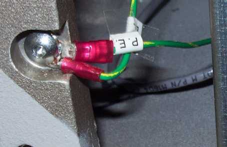
Figure 1 - Power Supply Ground Wires
3. Disconnect the two ground wires (marked P.E., one connected to the back of the power switch and the other to the terminal board on the side of the power supply unit) from the back of the machine body.

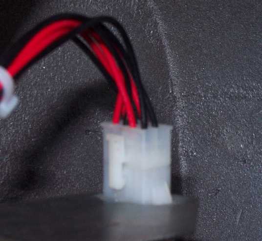
Figure 2 - Power Supply Harness Connection
4. Disconnect the power supply harness from the top of the power supply switch.
5. Remove the four M6x12mm cap head socket screws, M6 split lock washers, and M6 flat washers connecting the power supply mounting bracket to the lower bed body. Two are located to the front of the bracket and two on the bottom close to the rear of the machine.
|
|
CAUTION!! Do not disassemble the power input assembly other than to remove the entire unit from the machine. |
6. Remove the power input assembly and replace/repair any defective parts.
Power Input Assembly Component Replacement:
(click on the below links if you need to replace the respective component)
Power Input Switch Replacement
Power Switch Interface Harness Replacement
Power Supply Interface Harness Replacement
Power Input Assembly Installation:
1. Install the four M6x12mm cap head socket screws, M6 split lock washers, and M6 flat washers and connect the power input assembly mounting plate to the inside of the lower bed machine body. Tighten the screws to Melco Torque Specifications.
2. Connect the ground wire from the power switch terminal block and the terminal block on the side of the power supply unit to the back of the machine body as shown in Figure 1.
3. Connect the power supply harness to the connector on the top of the power switch bracket.
4. Install the lower bed rear cover and tighten the screws to Melco Torque Specifications.
5. Connect the A/C power input cord to the power input connector on the back of the machine.
6. Turn the power switch ON.
7. Verify that the power supply is fully functional using the procedures defined in Power Supply Test.
Power Input Assembly Removal | Component Replacement Links | Power Input Assembly Installation | Top of Page