 Getting Started Video
Getting Started Video
This section will introduce you to all of the different areas of the DesignShop user interface, and will help you become familiar with the layout of DesignShop before you begin learning about its tools and features. The following picture represents the default DesignShop menus and toolbars:
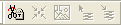
The toolbars on the left of DesignShop are the default toolbars. This first toolbar is the Input toolbar and consists of the following buttons: Edit Mode, Select Walk Input Method with Normal Stitch, Select Column 1 Input Method, Single Line Center Input Method, Select Complex Fill Input Method, Select Lettering Input Method, Insert Trim, Select Cross Stitch Input Method, Insert Outline Into Selected Object, Splice, Insert Entry/Exit Points, Insert Stitch Direction, Bezier Digitizing Mode, Freeform Digitizing Mode, Select Automatic Circle Input Mode, Select Automatic Rectangle Input, and Select Automatic Custom Shape Input. The second is the Palette toolbar and this controls your color palette.

Automatic Circle Input Video
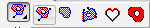
The Complex Fill flyout consists of the following tool buttons when you hold down the mouse over the little arrow on Complex Fill: Select Complex Fill Input Method (Traditional Input Method), Select Complex Fill Input Method (Manual Input Mode), Select Complex Fill Input Method (Unafill Input Mode), Select Applique Input Method, and Select Vector Fill Input Method.


The menu bar at the top of the DesignShop screen consists of a window icon, which provides access to the standard minimize application, maximize application, and exit application functions. The menu bar also contains eight different menus: File, Edit, View, Insert, Object, Graphic, Tools, Window, and Help.

These menus provide access to many of the tools and features that will be discussed throughout this help system.
Toolbars Video
If you would like show any of the toolbars the you do not see, you can turn them on by selecting View->Toolbars, then left-clicking on the individual toolbar names to show them. You can hide toolbars with these methods, too. If you double-click on a toolbar it will become a box that you can move around your DesignShop screen by left-clicking and dragging.
The Main toolbar consists of the following tool buttons: New File, Open File, Insert File, Save, Notes, ENS, Send to EP-4. Cut, Copy, Paste, Undo, Redo, Print, and Help.

The View toolbar consists of the following tool buttons: Zoom tools, Ruler, Display Hoop, Origin, Grid, Show in 3D, Hide/show Graphic, Hide/show Stitches, Toggle Connectors, Toggle Bezier Handles, Toggle Expanded Points, Wireframe Editing Mode, and Expanded Editing Mode.

The Object toolbar consists of the following tool buttons: Update Auto Tie/Trims, Center Design, Convert Graphic, Stitch Graphic Region, and Convert Vector Object(s) To/From Embroidery.
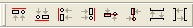
The Align toolbar consists of the following tool buttons: Align Top, Align Bottom, Align Left, Align Right, Center Horizontally, Center Vertically, Space Evenly Vertically, and Space Evenly Horizontally.
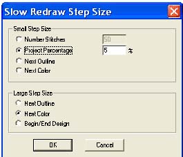
 Slow Redraw Video

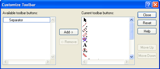
You can customize your toolbars to hide some of the tools or to change the order in which the tools are displayed. To do this, right-click on the toolbar you want to change. When the Customize pop-up menu appears, left-click on it. This is an example of a dialog that appears:
Status Bar Video
The status bar displays helpful information about your project. It tells you the placement of your cursor. The status bar also tells you helpful information on each tool if you place your cursor on a button in one of the toolbars. You can view what level of zoom you are at.
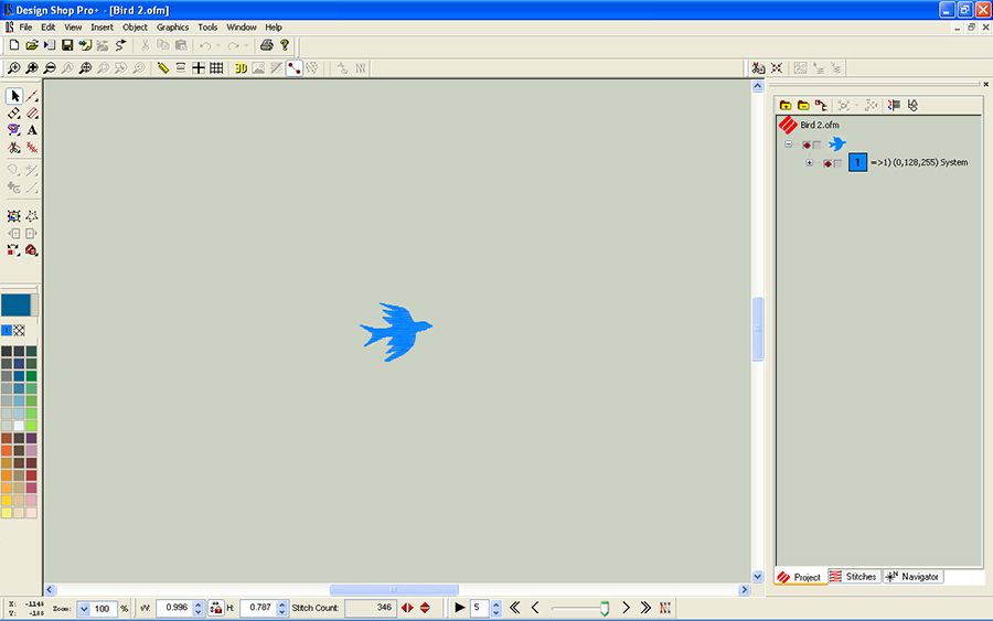
The View Window (the area in the middle of the DesignShop screen) is where you will view the project you are working on. The View Window can also be thought of as your work area or workspace.
You will perform most of your editing and digitizing inside the View Window. When you have a design open, you can right-click in the View Window to access some of the tools available in DesignShop. All of these tools will be discussed in this manual.
You can have multiple projects open at a time in Design Shop. When you have more than one project open, each of the projects will have its own View Window.
When you have multiple projects open, you can use the Window menu to select the project you want to view (select Window and the designs you have open are listed atb the bottom of the pop up). You can also use the Window menu to arrange multiple windows by tiling (select Window->Tile) or cascading (select Window->Cascade) them. You can also use the Window menu to close the project you are working in (select Window->Close) or to close all open projects (select Window->Close All).
Object
Properties Video
The Project View area is the white box on the right side of the DesignShop screen. If this box is not visible on your DesignShop screen, select View->Project Views to make it visible (you can also do this to hide it). You can also show/hide the Project View area by right-clicking in the gray area to the right of the toolbars and left-clicking Project Views in the pop-up menu.
The Project View area consists of three tabs: Project, Stitches, and Navigator. These tabs are designed to assist you while you are working on a project. To show/hide any of the tabs, right-click one of the tabs and left-click the name of the tab you want to show/hide in the pop-up menu.
 The Project
tab displays a tree view of everything that you have done within a project.
This tree view consists of four levels: the Project Level, the Design
Level, the Color Level, and the Element Level.
The Project
tab displays a tree view of everything that you have done within a project.
This tree view consists of four levels: the Project Level, the Design
Level, the Color Level, and the Element Level.
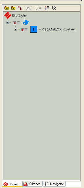
The highest level in the tree view is the Project Level.
The second level in a project is the Design Level. A project can consist of one or more designs.
The third level is the Color Level. This level tells you what color is assigned to each element. You can also insert color changes at this level by going to Insert->Color Change.
The fourth level in a project consists of the elements of each design. Each design can consist of one or more elements. The elements that make up a design can be Manual Stitch, Walk Stitch, Column1, Column 2, Complex Column, Singleline center, Singleline left, Singleline right, Complex Fill, Lettering, Color Change, Trim, and Return to Origin. All of these elements are discussed in more detail in this manual.
A plus sign (+) to the left of an object (e.g, an element) in the tree view indicates that the object contains a branch that can be expanded (by left-clicking on the plus sign or pressing the right arrow key on your keyboard). When a branch is expanded, you will see a minus sign (-) to the left of the object at the top of the branch. Click on the minus sign to collapse the branch (or press the left arrow key on your keyboard). You can also select an object, right-click on it, then select Tree Collapse Points from the pop-up menu. This will collapse all expanded branches at the lower levels of the tree view.
Use the up and down arrow keys on your keyboard or the scroll bar to move up and down in the project tree. You can also use the PAGE UP and PAGE DOWN keys on your keyboard to move up and down in the project tree. Press the HOME button to navigate to the first item in the tree, and press the END button to navigate to the last item in the tree.
If you are using the DesignShop or higher product level, you can perform editing on any project, design, element, or stitch list from within the tree view by selecting it, then right-clicking. You can also move items around in the tree by left-clicking them, then dragging and dropping them to the desired location.
 The icons
to the left of elements allow the user to show/hide a specific element
in the View window. Click in the box to show the red icon and show the
element. Click the box again to hide the element. The lock icon allows
the user to lock an element. If you choose either of these icons at the
highest design level it will perform the actions for all the elements
in the design.
The icons
to the left of elements allow the user to show/hide a specific element
in the View window. Click in the box to show the red icon and show the
element. Click the box again to hide the element. The lock icon allows
the user to lock an element. If you choose either of these icons at the
highest design level it will perform the actions for all the elements
in the design.
![]() The file icons with a + or -
on them allow the user to expand or collapse all the colors in a design.
The file icons with a + or -
on them allow the user to expand or collapse all the colors in a design.
 The Auto Merge Color
Blocks button allows the user to merge all like colors. See Color System for more information.
The Auto Merge Color
Blocks button allows the user to merge all like colors. See Color System for more information.
 The grouping icons allow the user
to group or ungroup elements in a design. To group elements, hold the
Control key
and click on the elements that are to be grouped together and then click
The grouping icons allow the user
to group or ungroup elements in a design. To group elements, hold the
Control key
and click on the elements that are to be grouped together and then click
 . The elements are now listed as "Group" in
the project tree view. Select the group and click
. The elements are now listed as "Group" in
the project tree view. Select the group and click  to ungroup
the elements.
to ungroup
the elements.
 The
Toggle Stitch Tab icon allows the user to make individual elements
or artwork visible in the project list. Turning this feature on shows
the Stitches tab next to the Project tab.
The
Toggle Stitch Tab icon allows the user to make individual elements
or artwork visible in the project list. Turning this feature on shows
the Stitches tab next to the Project tab.
 The Toggle Point List
button allows the user to make all the points in a design visible in the
project list. Clicking this button shows a + next to an element and clicking
the + you can view all the points in that element of the design.
The Toggle Point List
button allows the user to make all the points in a design visible in the
project list. Clicking this button shows a + next to an element and clicking
the + you can view all the points in that element of the design.
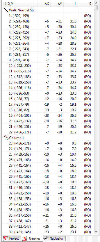
 The Stitches
tab was designed to aid you with stitch point editing. The Stitches
window shows all of the stitch points for an entire project. These
stitch points are editable in an expanded and wireframe elements.
The Stitches
tab was designed to aid you with stitch point editing. The Stitches
window shows all of the stitch points for an entire project. These
stitch points are editable in an expanded and wireframe elements.
To navigate through the expanded data list you can scroll using your mouse, or you can use the HOME, END, PAGE UP and PAGE DOWN keys (or the Up/Down Arrow Keys) on your keyboard. You can also press ALT + Up/Down Arrow Keys to move 10 stitches in the list, or CTRL + Up/Down Arrow Keys to move 100 stitches.
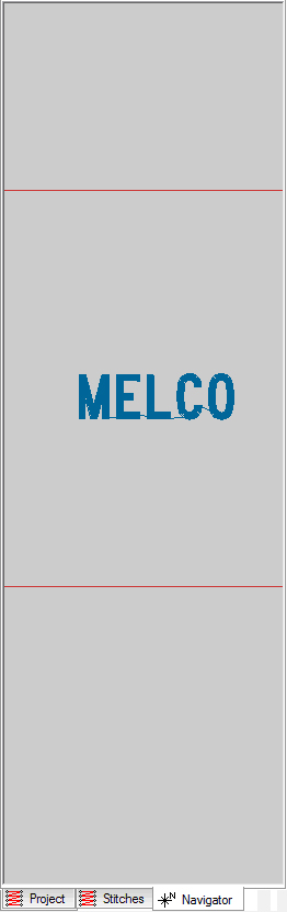
 The Navigator
tab is a very useful tool within the tree view. Here you will find a small
version (a thumbnail image) of your project. There are two ways of moving
within a project using the navigator tool.
The Navigator
tab is a very useful tool within the tree view. Here you will find a small
version (a thumbnail image) of your project. There are two ways of moving
within a project using the navigator tool.
One way to use the navigator is to left-click and drag while your cursor is in the view box (the red box). This view box represents the area that will be displayed in your View Window.
The second way to use the navigator is to left-click in the thumbnail image of the Navigator tab. The area that you click on will now be the center of the view box.
As you use the zoom tools in the View Window, the size of the view box in the Navigator tab will increase or decrease.
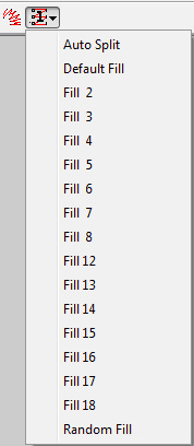
![]()