![]()
|
|
This procedure should be done only by an authorized Melco service technician. |
Repair Parts Needed:
presser foot assembly repair kit
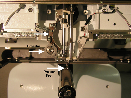
Figure 1 - Presser Foot Assembly Installed
1. When replacing the presser foot assembly, replace ALL of the parts that are in the presser foot assembly repair kit.
2. With the machine on, take the z-shaft to its HEAD UP position.
3. Turn the machine off.
4. Pull all of the thread out of the needles only and tie them all together in a knot at the bottom.
5. Remove the needle case access cover.
6. Remove the needlecase cover and let it hang on the bottom by the threads.
7. Loosen the top screws on both the left and right color change spindle mounting brackets.
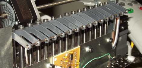
Figure 2 Wire Installed Through Take Up Levers
8. Slide a stiff wire (e.g., a piece of hanger wire) through the take up levers as shown above to keep the take up levers together (to make it easier to reinstall the needlecase later).
9. Slide the needlecase carefully to the left and allow the first two needles to drop.
10. Remove the right upper arm front cover.
11. Loosen the top and bottom M4x4mm flat point set screws that hold the presser foot shaft in place.
|
|
CAUTION!! Hold onto the spring as you remove the presser foot guide shaft. It might jump when the pressure on it is released. |
12. Remove the presser foot, bushing and spring by pulling them straight out of the upper arm casting.
13. Place the upper presser foot bearing in position on the presser foot for installation and hold it in place.
14. Place the presser foot assembly in place on the machine as shown in Figure 1 and start the guide shaft into the top bearing. Note the position of the upper portion of the presser foot with the reciprocator shaft.
15. Install a plain plastic bearing flange into the top of the spring.
16. Insert the spring and push the guide shaft through the spring into the lower presser foot bearing.
17. Turn the presser foot guide shaft until the flats at both ends face towards the front.
18. Pull the presser foot guide shaft down until it seats into the lower hole in the upper arm body.
19. Tighten the set screws on the top and bottom of the upper arm to Melco Torque Specifications. Make sure the top of the shaft is below the top face of the casting.
20. Make sure that the Z-shaft is at z-index position. Move the presser foot up and down to ensure it clears the color change sensor bracket.
21. Lift the needle bars that have dropped down one at a time so that the needle studs align with the others and slide the needlecase over to the right. When all of the needles are up and aligned, center needlecase. Lift the presser foot to clear the right side of the grabber.
21. Adjust the needle case left or right as needed so that the end of the color change spindle is even with the outside edge of the right color change spindle mounting bracket.
22. Tighten the top screws on both the left and right color change spindle mounting brackets to Melco Torque Specifications.
23. Install the needle case cover and access cover.
24. Pull the slack out of the threads and press them into the thread retaining spring located on the front of the needlecase cover, cutting the excess right at the spring.
25. Turn the machine on.
26. Go to bottom dead center in the Maintenance Menu in the AMAYA OS software and verify left and right needle centering in the needle plate hole.
|
|
Note: The above procedure is based on the assumption that left to right needle centering was correct before the screws on the color change spindle mounting brackets were loosened. |
27. You now need to verify the distance from the needle to the presser foot. The nominal distance from the centerline of the needle / needle bar to the lowest inner surface of the presser foot is 2.5mm.
One way to verify this distance is described below.
28. Replace any needle with a drill blank (or straight wire) with a diameter of 1.6mm (0.0625in) and a length of approximately 30mm (1 3/16").
29. By rotating the upper z-shaft, move the corresponding needle bar down until the presser foot reaches its lowest position.
30. The distance between the drill blank and the inner surface of the presser foot should be approximately between 1.5mm and 2mm. To check this distance, first place a 1.5mm (1/16") hex wrench between the drill blank and the presser foot.
If the hex wrench does not fit, the distance is too small (proceed to step 31).
If the hex wrench fits, you then need to verify that the distance is not too large. To do this, place a 2mm (5/64") wrench between the drill blank and the presser foot. If it fits snugly, the distance is correct. If it fits loosely, then this distance is tool large (proceed to step 32).
31. If you determine that the distance needs to be adjusted, carefully bend the presser foot in the appropriate direction, then repeat step 30 to check the distance. Repeat this process until the distance is corrected.
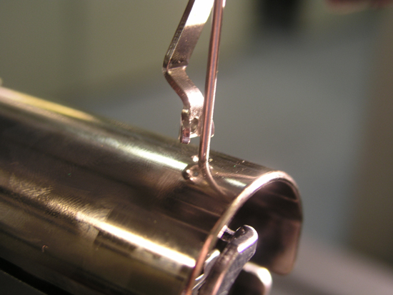
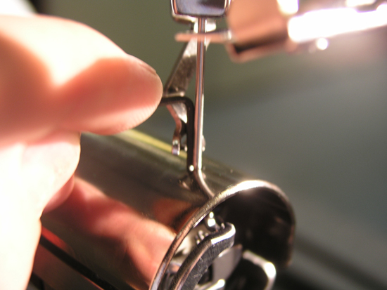
32. Verify that the presser foot is not interfering with the grabber trap (see image below).
33. To adjust the presser foot height if needed, click here for instructions.
![]()