![]()
|
|
This repair requires timing and other adjustments and should be done only by a Melco authorized service technician. |
The only reason for removal of the x-carriage assembly is to replace the bearings, located on top of the carriage, if they are damaged. Damage will usually result from an x-motor fault that causes it to runaway, operator error, or some kind of impact to the x-carriage assembly. When this happens, the bearing might develop some "flat spots" that make the carriage move left or right roughly. Damage can also be caused from fretting corrosion due to misalignment of the bearings or lack of proper lubrication (see "Carriage Rail Lubrication").
|
|
Note: If corrosion of the carriage rails occurs, the x-beam assembly must be replaced using procedures prescribed in "X-Beam Assembly". |
Replacement Parts:
two rear straight linear bearing assemblies (PN: 30781-03)
two front straight linear bearing assemblies (PN: 30782-03)
Removal/Repair Procedures:
|
|
Note: When the linear bearings are damaged, all of them will usually sustain the same damage. It is recommended that you replace all four bearing assemblies at the same time. |
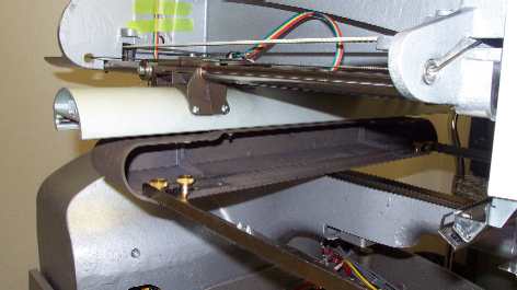
Figure 1 - X-Beam and Carriage Assemblies Installed
1. Turn the machine OFF.
2. If installed, remove the hoop and both hoop arm assemblies.
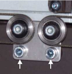
Figure 2 - Remove Two Screws on Cable Pulley Bracket
3. Loosen and remove the two screws holding the cable pulley bracket in the rear center of the x-carriage assembly.
4. Remove the x-beam end cap from the right end of the x-beam.
5. Slide the x-carriage assembly out of the x-beam from the right side of the beam.
6. Remove the damaged straight linear bearings and replace them with new bearing assemblies. Install the bearing nuts and washers and leave the nuts loose until the x-carriage is installed on the x-beam.
7. Slide the x-carriage assembly back into the x-beam assembly.
8. Adjust the front two bearings with an Allen wrench.
a. The front bearings have an eccentric stud that is turned counterclockwise to tighten the fit between the two bearing rails permanently installed in the x-beam. This stud is used to adjust the front to back fit of the x-carriage in the beam.
b. Tighten the nut on the back bearings just enough to keep the stud in position vertically.
c. With the Allen wrench, turn the stud counterclockwise until the front to back fit between the two rails is tight (no freeplay) and tighten the nut to Melco Torque Specifications. Adjust the carriage so that it moves freely left and right without any resistance, but no freeplay is noticeable when you try to move the carriage front to back in the x-beam.
|
|
CAUTION!! Adjusting the bearings on the carriage accurately to the x-beam is very important. Too much play between the bearings and the rails in the x-beam can result in damage to both components. |
d. Tighten the nuts on the rear bearings to Melco Torque Specifications.
e. Lubricate the rails in the x-beam using the procedures prescribed in "Carriage Rail Lubrication".
9. Install the right x-beam end cap onto the x-beam.
10. Install the cable pulley bracket back onto the rear of the x-carriage assembly with the two cap head socket screws and tighten the screws to Melco Torque Specifications (Figure 2).
11. Turn the machine ON.
12. Run a short functional test (about two minutes worth) and verify proper x-axis movements and that the carriage moves left or right smoothly.
13. Run the following sew tests on the AMAYA:
![]()