You can edit column properties at the project, design, and element level (element level editing is only available in the DesignShop and higher product levels).
 Column Properties Video
Complex Fill Properties
Video Part 1
Complex
Fill Properties Video Part 2
Complex
Fill Properties Video Part 3
Complex
Fill Properties Video Part 4
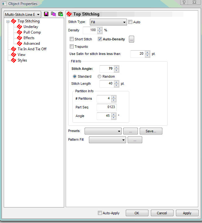
Stitch Type: You have the option of choosing from five different stitch types: Satin, Fill, E Stitch, Edge Fill, Tackle Stitch, and Zigzag. See below for the Top Stitching tab if you check Auto.
Fill
Stitch Type Video
Satin
Stitch Type Video
Zigzag
Stitch Type Video
Use Satin for stitch lines less than: Allows you to specify when to use Satin stitches for stitch lines less than a certain number of points.
Short Stitch: When digitizing columns, particularly letters or numbers, stitches will build up on the inside of a sharp arc or turn in the design. This build-up often causes thread breaks because stitches begin to fall on top of each other at the same location. Even if thread breaks don't occur, the look of the stitching may not be ideal. Using the short stitch option prevents this build-up by inserting shorter stitches throughout the curve or turn making it a much smoother transition. The software determines where short stitches should be inserted based on the relative length of the sides of a column segment, their length as a percentage of the actual distance across the column, and how many will be generated between any two normal length stitches, as shown in the example on the next page.
The default setting is for short stitches to be On because short stitches will only be generated where the software determines short stitches will be needed to prevent stitches on top of stitches. If you would like to turn short stitches Off, left-click in the box next to the short stitches option.
Auto-Density: Many columns are not going to be straight from beginning to end. The width may increase, decrease, and increase again. In this situation it is very useful to use the Auto-Density option, instead of having to manually insert density changes throughout your stitchlist. Auto density will determine the density changes for you. To implement the Auto-Density function, left-click in the box. Click again to remove the check mark (this turns Auto-Density off). Below is an example of Auto-Density turned on.
 button next to Auto
Density brings up the following dialog.
button next to Auto
Density brings up the following dialog.
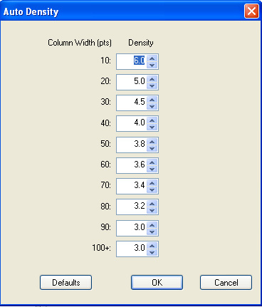
Auto Density Video
Trapunto: Trapunto allows you to move the travel stitches of a complex fill to the side of the element, instead of through the middle. This will prevent the travel stitches from being conspicuous on larger space values or higher density fills. Click to insert a check mark in the box next to Trapunto to apply this type of underlay, click in the box again to remove Trapunto. Below is an example of a complex fill with Trapunto applied. Trapunto only shows if you are working with a Fill or an Edge Fill.
 gives you a preview of the different fills. Clicking
on
gives you a preview of the different fills. Clicking
on  allows
you to save a fill as a new style.
gives
you a preview of the pattern fills. See Pattern
Fills for more information.
allows
you to save a fill as a new style.
gives
you a preview of the pattern fills. See Pattern
Fills for more information.
Fill Info: You can choose between Standard or Random fills. If you choose Random Fill, you must specify the type (Pattern Less, Random Offset, or Random Stitch Length).
Density: Density refers to the space between each line of stitching. When this space is decreased, the lines of stitching per inch increases. To create more lines of stitching per inch, decrease the density value. A general rule of thumb is:
As design size increases, density value should decrease.
As design size decreases, density value should increase.
Density Video
Stitch Length: This allows you to set the stitch length for the fill.
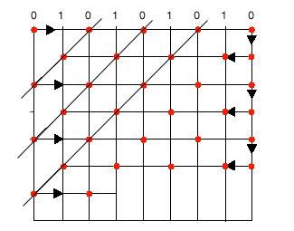
# Partitions: Partition lines is a mathematical term, and the lines are seen only by the computer. The partition lines are used to determine where the needle will penetrate on each stitch line. Partition lines are numbered beginning with 0; you can enter up to 8 partitions in this field.
Each row of stitching consists of needle penetrations made from one partition line. The number of rows in a partition line set always equals the number of partition lines. In the example below, the number of partition lines is 2; therefore 2 rows of stitching make up the partition lineset. The two partition lines in the illustration are numbered 0 and 1.
In the 1st stitch line, the needle penetrates at the intersection of the stitch line and partition line 0.
In the 2nd stitch line, the needle penetrates at the intersection of the stitch line and partition line 1.
The needle repeats this sequence each 2 stitch lines.
The partition line sequence is 0,1,0,1,0,1, etc.
Part Seq: If you look closely at the finished fills, you will be able to distinguish a visual pattern. You can vary this pattern by changing the stitch length and density, and by changing the angle of the partition lines; but going one step further, you can change the sequence of the partition order, i.e., 0, 1, 2, 3, 4, 5, 6, 7. For example, you could change the sequence in the previous example to 1,0,1,0, etc.
NOTE: When you create your own partition sequence, if you include a number that is higher than the number of partition lines, that number will be ignored. For example, if you choose 6 for the number of partitions, a 7 in the partition sequence would be ignored.
Angle: The angle made by the intersection of any given partition line with the line of stitching in a fill pattern. The angle is measured in a counter-clockwise rotation from the left end of the line of stitching. The angle can be any number between 1 degree and 179 degrees.
In the example below, the partition line angle is 45 degrees, because each stitch point of the partition lines up at an offset that makes a 45 degree angle when a line is drawn through each stitch point of the partition line.
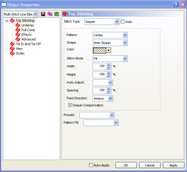
Stitch Type: Allows you to specify Sequin as the stitch type.
Pattern: Allows you to choose the sequin pattern.
Shape: Allows you to choose the sequin shape.
Color: Allows you to choose the sequin color.
Stitch Mode: Allows you to choose Fill or Edge Fill for the sequin stitching mode.
Width: This feature is adjusted automatically to scale the width of your sequin fixing stitch pattern between the width it was digitized and the selections you specified with the stitch and sequin types.
Height: This feature is adjusted automatically to scale the height of your sequin fixing stitch pattern between the width it was digitized and the selections you specified with the stitch and sequin types.
Auto-Adjust: Allows you to auto-adjust the sequin spacing.
Spacing: This feature is adjusted automatically to scale the spacing of your sequin fixing stitch pattern between the width it was digitized and the selections you specified with the stitch and sequin types.
Feed Direction: This feature defines the direction that the embroidery machines feeds the sequins. This needs to be set for the type of machine you are digitizing for. The choices from the drop down menu are: AMAYA (used for all AMAYA machines), North (used for all Shiffli machines), and South (used for all multi-head machines).
Sequin Compensation: When this box is checked the stitch pattern automatically adjusts for the sequin feed direction. The default is checked.
Presets:
This gives you a drop down list of existing fills that you can use for
your design. Clicking on gives you a preview of the different
fills. Clicking on allows
you to save a fill as a new style.
gives
you a preview of the pattern fills. See Pattern
Fills for more information.
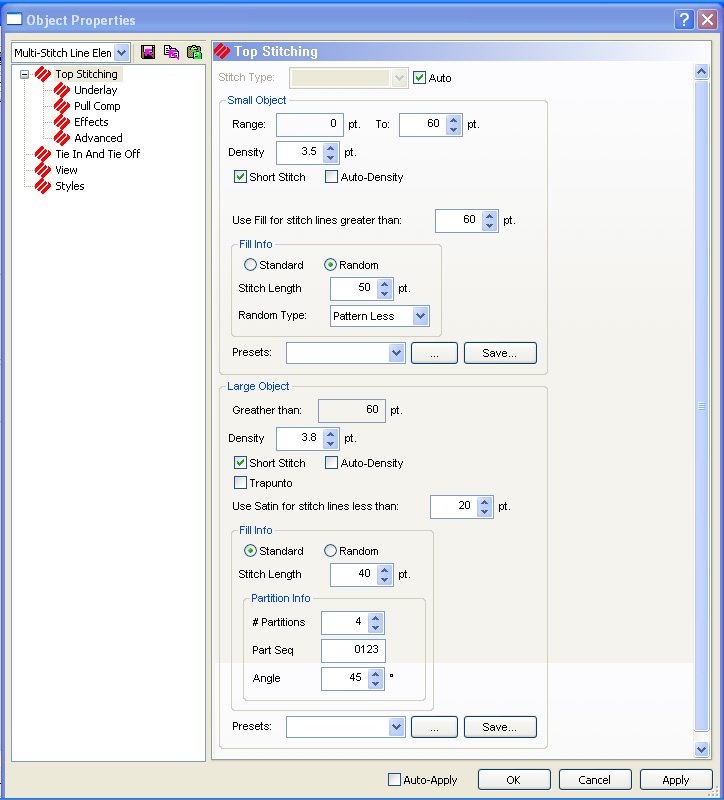
When Auto is checked, DesignShop automatically chooses whether to sew a design as a Satin or as a Fill, depending on the parameters set and the size of the object. For example, if the range for small objects is 0 to 60 points, then any part of a design under 60 points sews as a Satin stitch and the parts of the design over 60 points sew as a Fill. The size of the object determines how that part of the design should be sewn automatically. You can specify the parameters for both small and large objects. See above for a description of each field.
Underlay Video
Underlay involves the stitches used to stabilize the fabric when sewing designs. The Underlay tab allows the user to change the settings for the underlay in each design.
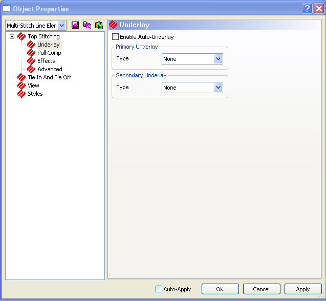
Enable Auto-Underlay: If this box is checked, you see the following dialog.
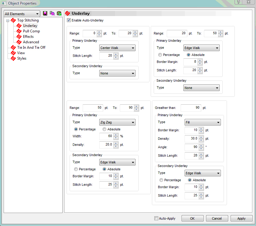
This dialog allows you to set point ranges and assign specific types of underlay to each range. Then DesignShop automatically uses the underlay specified based on the size of the object.
Primary Underlay: You have the options of choosing 5 different kinds of primary underlay from the drop down menu: ZigZag, Fill, Center Walk, Edge Walk, and Double ZigZag.
Stitch Length - The maximum stitch length between underlay needle penetrations
Border Margin - The area between the edge of the underlay and the edge of the fill.
Density - The number of embroidery points there are between rows of stitches in the underlay. (Does not apply to Edge Walk.)
Angle - The angle of the underlay is in relation to the stitch direction of the fill. For example, a 90 degree angle underlay will be sewn perpendicular to the stitches of the fill. (Does not apply to Edge Walk.)
Secondary Underlay: You have the options of choosing 5 different kinds of primary underlay from the drop down menu: ZigZag, Fill, Center Walk, Edge Walk, and Double ZigZag.
Stitch Length - The maximum stitch length between underlay needle penetrations
Border Margin - The area between the edge of the underlay and the edge of the fill.
Density - The number of embroidery points there are between rows of stitches in the underlay. (Does not apply to Edge Walk.)
Angle - The angle of the underlay is in relation to the stitch direction of the fill. For example, a 90 degree angle underlay will be sewn perpendicular to the stitches of the fill. (Does not apply to Edge Walk.)
If you do not check Enable Auto-Underlay you still choose from the 5 different kinds of primary and secondary underlay: ZigZag, Fill, Center Walk, Edge Walk, and Double ZigZag. Each underlay choice has different parameters for you to set. Make your selections and click OK or Apply.
Pull Compensation Video
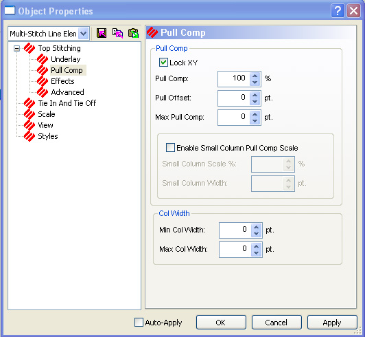
Lock XY: Check this box to adjust the pull compensation and pull offset proportionally in both the X and Y directions. If this box is unchecked, you can adjust the pull comp or pull offset in each direction separately.
Pull Comp: The primary use of this feature is to compensate for the pull of the stitches on material. When the pull compensation value for a given object is changed, all adjustments will be made with respect to each individual stitch line length and direction. Because the adjustment is based on a percentage, the longer the stitch line, the more compensation is added. For example, if the pull compensation is set to 105% for an object, each individual stitch line will be increased in length by 5% with respect to its current stitch direction. This is based on the idea that longer stitch lines pull harder on material than shorter lines.
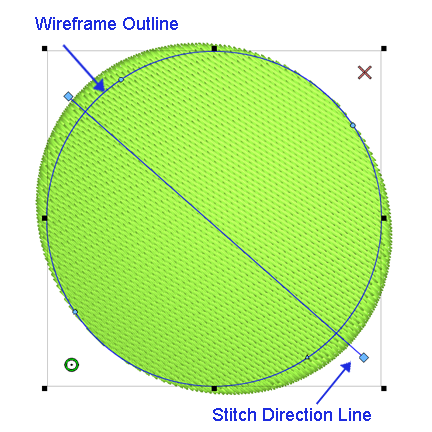
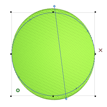
To visualize how the stitches compensate in relation to your stitch direction, grab one end of your stitch direction line and rotate it to another position. Also, watch how pull compensation affects the stitches of an element with multiple stitch directions, like a column.
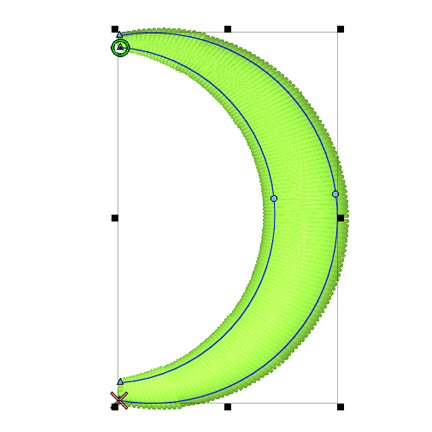
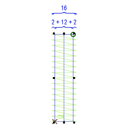
Pull Offset: Pull Offset is another way to adjust for the pull of stitches. Pull Offset allows you to enter a specific value in points. Pull Offset will add that value to each end of stitch lines, extending them evenly throughout the element or elements. For example, if a pull offset value of 2 pts was added to a single-line column with a width of 12 pts, the stitch lines of the column would be extended to equal 16 pts.
* Adding pull comp and/or pull offset can help alleviate the distortion that happens from stitches pulling on the material. When a circle is digitized and then sewn, it is not uncommon for the sewout to look a bit ovoid. With pull comp or offset added, the sewout looks much more circular.
* Adding pull comp and/or pull offset can also be helpful when a design with outlines isnt lining up. Adding that bit extra will sometimes allow the layers to overlap and appear to line up again.
* Adding a few points of pull offset can be very useful in helping small lettering and thinner columns sew out more smoothly.
Max Pull Comp: This value will limit how far the pull compensation is allowed to extend the stitch lines. This means that if a 20 pt. value was entered for the max pull comp, the longest lines would stop at 20 pts. Past the wireframe outline, even if the percentage entered in the pull comp field would have cause the stitch line to extend past that.
Enable Small Column Pull Comp Scale: If this is checked, the pull compensation will increase for small columns based on the values specified.
Small Column Scale %: This is where you specify how much you want the pull compensation to increase.
Small Column Width: This is where you specify the width of the small column.
Column Width
Min Col Width: The Minimum Column Width will keep stitch lines in a column from falling shorter than the value entered in the Min Col Width field.
Max Col Width: The Maximum Column Width will keep stitch lines in a column from being longer than the value entered in the Max Col Width field.
This section describes the effects available for fills and columns: random edge, distortion effects, and custom density. These effects can be accessed by clicking the Effects button on the property page.
Random Edge is very useful in embroidery to create the effects of shading, the look of hair and many other possibilities.
Random Edge allows you to specify a fill edge stitch length variance. This means one or both sides of a fill are randomly zig-zagged in and out instead of the usual even fill edge. This effect can be applied to side one, side two or both fill sides. Random Edge applies to all of the following fill stitch types: Pattern, Standard, Satin, and Decorative.
When applying Random Edge to a fill, select Edge One, Edge Two, or Both edges. Next select the width percentage from 0 to 100%. The width percentage represents the range of variation width.
NOTE: The Random Edge Data cannot be saved as part of a condensed file.
The following image displays an example of Random Edge used with a fill:
(Available only in the DesignShop Pro + level)
The wave fill function allows you to create a curved stitch direction line, producing a stitch direction with one or more curves.
To create a wave fill:
Select a complex fill.
Position the mouse over the center of the stitch direction line.
Input one or more straight (left-click) or curved (right-click) points.
Select a point on the stitch direction line and move it to the desired location. The stitch direction will reflect the changes to the stitch direction line.
You can also change the length of the stitch direction line, which will alter the repetition of the waved effect (i.e., if the stitch direction line is shorter than the width of the fill, the waved effect will repeat.
(Available only in the DesignShop Pro + level)
Double wave fills are similar to wave fills, in that double wave fills can have a curved stitch direction line. The difference between the two types of effects is that double wave fills can have multiple stitch direction lines. Because double wave fills can have multiple stitch direction lines, there can be multiple variations of the curved stitch direction.
To create a double wave fill, see Using Double Waved Fill Effect.
(Available in DesignShop Pro and higher product levels)
This fill effect allows you to apply visual perspective to complex fills (e.g., you may want the top of a fill to appear like it is farther away than the bottom of a fill).
NOTE: This fill effect works best with decorative fills.
To create a perspective effect, see Using Perspective Fill Effects.
As with double wave fills, you can add points to the stitch direction lines to create curved stitch directions.
NOTE: The stitch direction lines can intercept the fill, but if the lines connecting the stitch direction lines intercept the fill, the fill will not sew properly.
(Available in DesignShop Pro and higher product levels)
This fill effect creates the appearance of a three-dimensional globe within a complex fill.
NOTE: This fill effect works best with decorative fills.
See Using Radial Fill Effects for more
information.
Notice the difference between the two fills below. The image on the left
is a fill with no effect, and the image on the right displays the Radial Out effect.
|
|
|

The quickest way to select the center and radius points is to select them from the Project Tree View.
(Available in DesignShop Pro and higher product levels)
This fill effect creates the appearance of a three-dimensional inward globe within a complex fill.
NOTE: This fill effect works best with decorative fills.
See Using Radial Fill Effects for more information.
The Radial In effect looks like this:
(Available in DesignShop Pro and higher product levels)
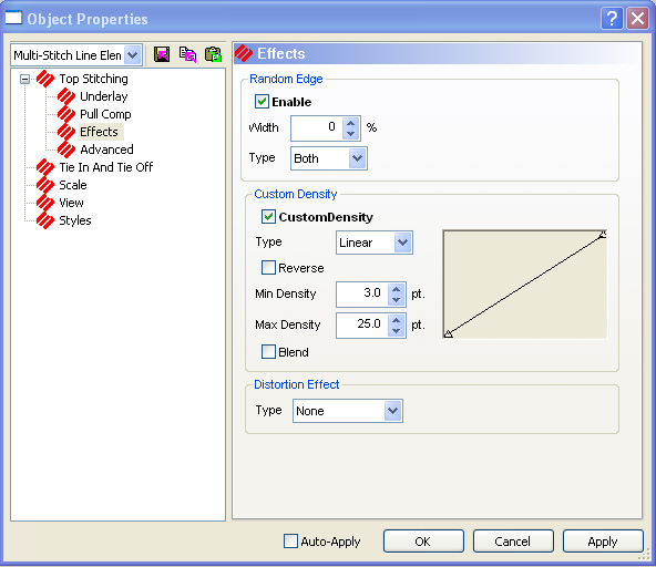
Custom Density allows you to specify variable density. This is often used for color blending. This will apply to all of the following fill stitch types: Pattern, Standard, Satin, and Decorative.
NOTE: Custom Density Data cannot be saved as part of a condensed file.
Custom Density is available on the Effects tab.
Custom Density is described in detail in Digitizing Columns. (See Column Effects, Custom Density)
Auto-Blend: To use Auto-Blend, click in the checkbox after selecting a custom density. Two colors are then stitched on top of each other with a blending effect using selected custom density values.
Capped and Mitered Cornering are for Singleline and Column1 type columns. These two methods of stitching around corners give DesignShop the ability to drastically change its direction of stitching without taking anything away from the stitch quality or appearance.
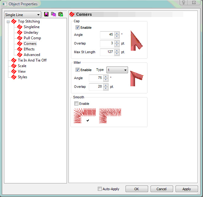
Capped Corners look like there is a "cap" over the area where two columns meet at a point. By inserting a degree value (45 degrees for example) for Capped Corners, you are telling Design Shop that you want the corners of singleline or column 1 columns to have Capped Corners once the angle is 45 degrees or smaller.
You also have the ability to determine how much the overlap should be (3 points for example). Refer to the example below to visualize the overlap of a Capped Corner. The following example has a very loose density and exaggerated overlay values on the stitches view for better visualization. The highlighted area illustrates the overlay area.
You have full control over these features via the Column Effects property page, which gives you the ability to toggle each feature. You can also control on which angles capping and mitering will occur, allowing one method to take precedence over the other.
Column 1 and Singleline corners only have the ability to be capped and/or mitered if a pair of straight points binds them. A mismatch of points (i.e. a straight point on the inside edge and a curved point on the outside edge or vice versa) or a pair of curved points will result in our current standard method of cornering being applied. For automatic smooth cornering to occur the corner must be bound by straight points and must have straight edges.
You can have multiple types of corners turned on and set for different degrees of angles.
Mitered Corners can be described as two columns with slanted edges that match up or blend together at the corner (imagine how a corner comes together on a picture frame; this is what the stitches will look like on a Mitered Corner when it is sewn out). By inserting a degree value (75 degrees for example) for Mitered Corners, you are telling DesignShop that you want the corners of Singleline or Column 1 columns to have Mitered Corners once the angle is 75 degrees or smaller. Refer to the example below to better understand the angle value.
You also have the ability to determine how much the overlap should be when the two edges of a Mitered Corner meet (20 points is an example). Refer to the example below to visualize the overlap of a Mitered Corner. The following example has a very loose density and exaggerated overlay values on the stitches view for better visualization. The highlighted area illustrates the overlay area.
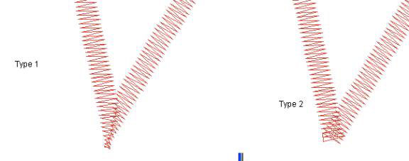
There are two mitering methods that you can choose from: Type 1 and Type 2 in the Mitering Method drop down box. Type 1 ends in a point and has different overlap than Type 2. Below are examples of each:
Automatic Smooth Cornering is for Singleline and Column 1 type columns. This involves automatically inserting pairs of straight points on each corner edge to allow for smoother stitching around the corner. Automatically inserted points may be converted to wireframe points by right-clicking on the element and selecting Convert Corners to Wireframe.
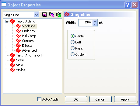
Width: This gives you the option of changing the width measurement for Singleline center, Singleline left, and Singleline right columns.
You can also change the position of the stitch area surrounding the column line by selecting Center line, Left of line, or Right of line.
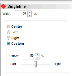
Custom: When you select the Custom radio button, you see a Width: control. This allows you to position a singleline column to the left and right of the center line by percentages.
For more information on digitizing Singleline Columns, click here.
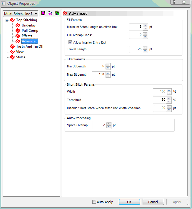
Fill Params
Minimum Stitch Length on stitch line: This controls how close the last stitch on a fill line gets to the edge of the fill. Increase the number to keep the last stitch further from the edge of the fill and decrease the number to move it closer to the edge of the fill.
Fill Overlap Lines: This field adds overlap to the edge of a fill. It has to be an even number.
Allow Interior Entry Exit: If this is checked, DesignShop allows you to have entry and exit points inside a design.
Travel Length: This controls the stitch length on a travel stitch. Increase the value for a longer travel stitch length.
Filter Params
These values apply when a design tapers into nothing. The values control if a stitch is deleted or added when it falls out of the set parameters.
Min Stitch Length: A stitch is deleted if the distance falls below this value.
Max Stitch Length: A stitch is added if the distance is greater than this value.
Short Stitch Params
Width: Increase this value for short stitches to sew closer to edge of a design. Decrease this value to keep short stitches further from the edge.
Threshold: This percentage is based on the average of the long side and short side lengths. Short stitches will be added if the distance is less than specified percentage.
Disable Short Stitch when stitch line width less than: This disables short stitches being added if the width is less than the value specified.
Auto-Processing
Splice Overlap: This controls how far a splice stitch overlaps in a design. The greater the value, the greater the overlap.
![]()